Description
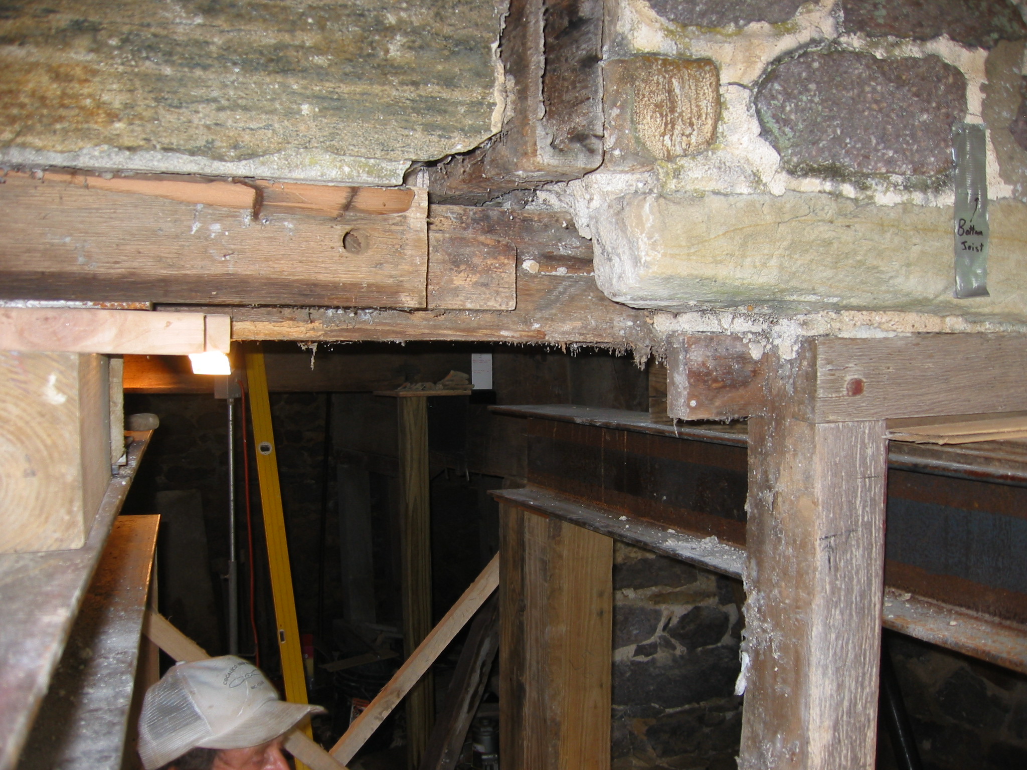
View between doorway and window openings in east cellar kitchen wall after removal of masonry abutment{1}.
The temporary steel I-beams [lower left corner and lower right quadrant of photo] on wooden shoring posts are positioned for temporary support of the kitchen's east wall structures during removal and restoration of the masonry piers flanking the kitchen door. The pier between the window and door jambs has been removed and was later re-laid in plumb alignment [see restored views in DTR09PH54--1001.01.138, DTR09PH55--1001.01.139, and DTR09PH97--1001.01.189]. The tenon ["ear"] at the north end of the doorway lintel [upper center of photo, below north outlooker remnant] appears in its modern position, but will be lowered about 4 inches to the original elevation in a "pocket" in the restored masonry pier north of the doorway. The "ear" at the upper left corner of the window frame projects from a pegged mortise-and-tenon corner joint [lower right quadrant of photo]. The restored door lintel will be at the same level as the window lintel ["header"], as they probably were aligned originally.
The embedded pair of "wall plates"{2}, serving here as a temporary shoring beam, is visible behind the doorway lintel and to the right [north] of its "ear" [tenon]. Their essential functions are to serve as relieving lintels, a composite form of bearing beam which transfers structural loads across the window and door openings to their masonry abutments{3}; as bearing and leveling timbers for the floor joists; as "ties", or framing members which tend to bind (here by virtue of the compressive forces bearing on them) adjoining masonry wall segments in mutually stable equilibrium; and as "bond timbers"{4, and see footnote 2 below}, which utilize the loads they bear to compress and interrupt ["break"] vertical mortar joints, reducing the potential for radiating fractures through long failure-paths in contiguous mortar joints{5}.
Square steel plates of varying thicknesses and wood blocks serve as leveling shims between the I-beams and wall plate during restoration.
FOOTNOTES:
{1} SEE DTR09PH4--1001.01.124 and DTR09PH41--1001.01.125 for pre-restoration views; and DTR09PH55--1001.01.139 and DTR09PH56--1001.01.140 for restored views.
{2} classically, "bond beam"; "bond timber"; "wall plate" is more commonly used to denote the top beam on a masonry wall which receives and supports the lower ends ["feet"] of roof rafters; and among craftsmen "spreader plates", for their function of distributing structural loads over a greater bearing area and across vertical mortar joints [see DTR09PH122--1001.01.218 and DTR09PH123--1001.01.219 for interior views of these plates].
The lower and shorter member of these stacked timbers serves as a relieving lintel over the door and window openings. The upper and longer member further relieves these openings of floor and wall loads above them, and distributes these loads over a larger masonry bearing area and spans a significant number of masonry joints.
Dimensionally, these timbers are similar to 3 inches x 9 inches floor joists laid flat [the joists at both floor levels average 3 inches by 9 inches, some slightly larger, ignoring chamfers]. Although "stacked", this pair of timbers is not technically "laminated," since no adhesive is involved. They would produce a greater bearing capacity if they were rotated 90 degrees, which would almost double their tensile strength without adding timber because of the mechanical principle that the bearing capacity of a beam is proportionate to its width only as a single factor, but to the square of the vertical depth of the beam. As a general proposition, a beam of the same material, length, and width as another beam but twice its depth is FOUR times as strong in bearing capacity ["tensile strength"].
This pair of timbers would have functioned better had they been rotated 90 degrees, for the reason discussed above, and mechanically connected to avoid independent deflection or lateral displacement of one or the other, as occurred here. As sized and aligned, they were inadequate to prevent the "tectonic" de-lamination of wall segments, lateral shifts and vertical dislocations in the east eaves wall and fireplace pier. These destabilizing movements cracked and crushed wall stones and the door sill, distorted the kitchen window oak sill, and distended several ranges of the rubble masonry walls.
However, the double-plate was not as critical among the causes of the deflection of the northern range of the east kitchen wall as the mortar degradation resulting from repeated saturation from ground and roof runoff and the cyclically high water table. These factors were primary and proximate causes of the loss of integrity in the wall as the lime content of the mortar gradually dissolved, leaving a weakly-bonded sandy "mud" in the masonry beds and joints.
Rural builders in the region had limited access to theoretical axioms governing structural design, and no "materials testing" calculations or stress tables to guide them in sizing timbers, but depended on inherited tradition, empirical experience, and often over-sized or otherwise redundant support systems in erecting "vernacular" structures without an architect or seasoned “housewright” or master-level craftsman overseeing the project. In most such instances the house or ancillary building was built without a "pattern" book or manual, which in the eighteenth century tended to describe and illustrate buildings of greater classicism, formality, and complexity than this modest multiple-use building.
See discussion in note {4} to DTR09PH40--1001.01.123 regarding the deficiencies in sizing and aligning these plates.
{3} These plates and the loads they support do not bear on the window frame, but rest directly on the masonry piers flanking the openings. Since the plates are about 9 inches wide [horizontally] and the lintels about 4 inches, the shorter relieving plate and the longer joist-bearing timber carry at least two-thirds of the wall, roof, and floor loads across the openings. The white oak jambs and lintels, functioning as post-and-beam assemblies, support the outer layer of the wall and its conjugate loads, which constitute less than one-third of the aggregate mass borne by these elements [see photo record DTR09PH92--1001.01.184, photo #1633].”
The original white oak window frame [“buck”] suffered little damage or deflection from the descent of the masonry and its embedded timbers, but the interior sill was deformed by the downward rotation of the masonry wall and its superincumbent loads north of the window [see photo DTR09PH11--1001.01.092.]
{4} A term dating from the Anglo-Saxon period and still appearing in the timber-framing vocabulary into the 2nd half of the 19th century.
{5} The absence of similar "ties" or an embedded "wall plate" in the north gable wall may have facilitated the uninterrupted two-story "lightning-bolt" crack near the northeast corner [see Atlas sheet #52, ground level plan, note: "wall cracked…"].
Catalog details
- Catalog number
- 1001.01.132
- Alternate number
- DTR09PH48
- Accession number
- 1001.01
- Date
- 7/29/2009
- Creator
- Larry Ward
- Object name
- Print, Photographic
- Record type
- Standard
- Classification
- Documentary Artifact