Description
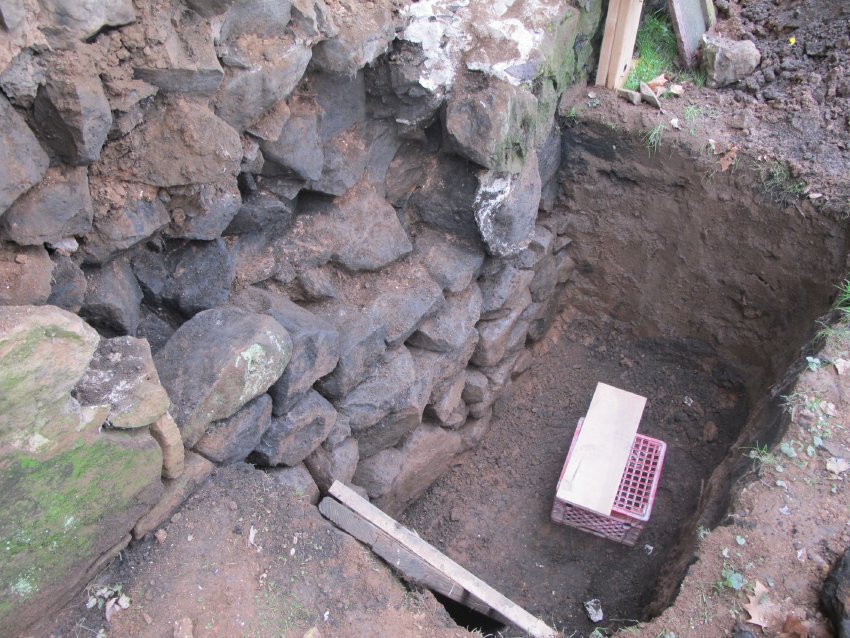
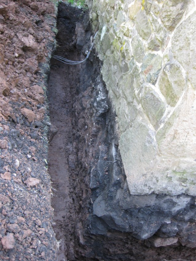
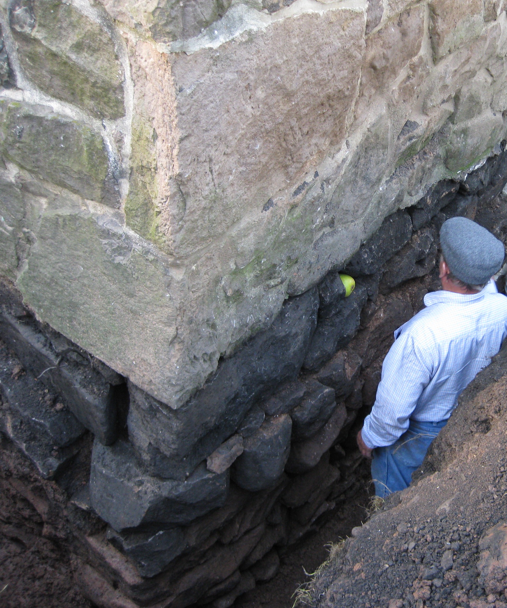
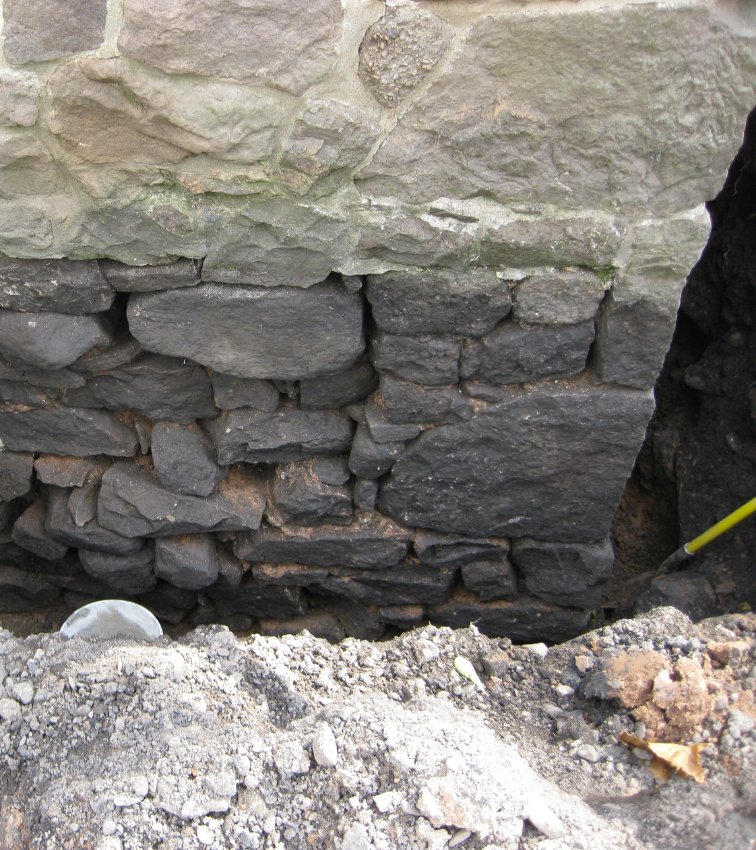
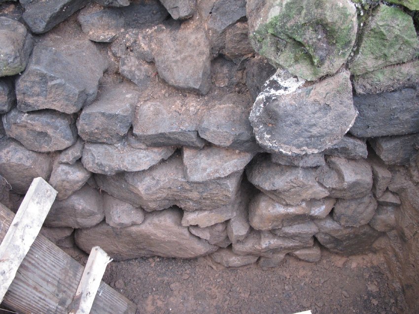
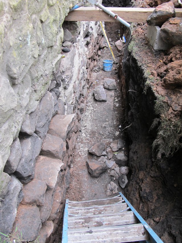
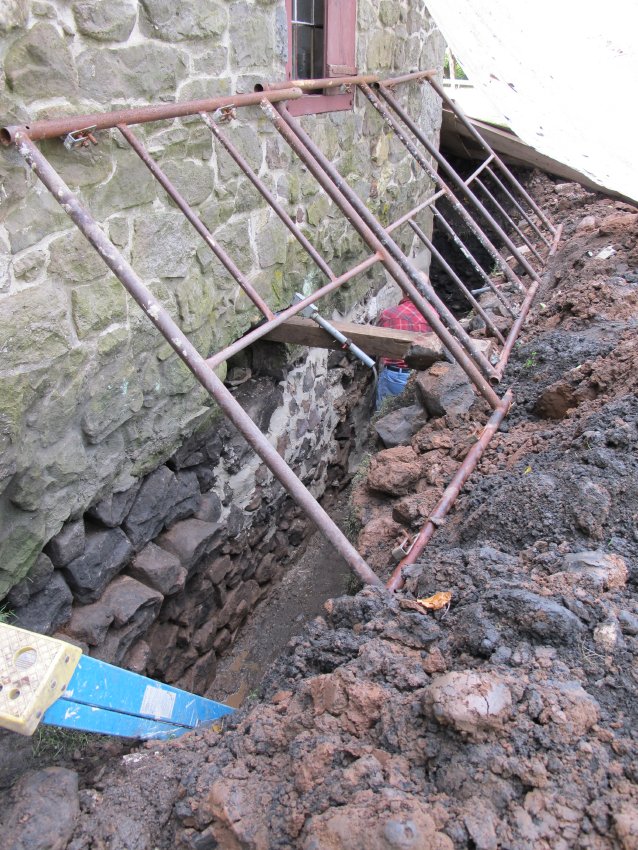
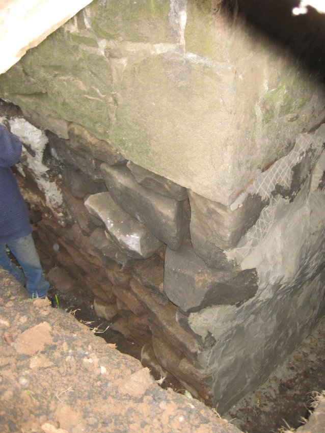
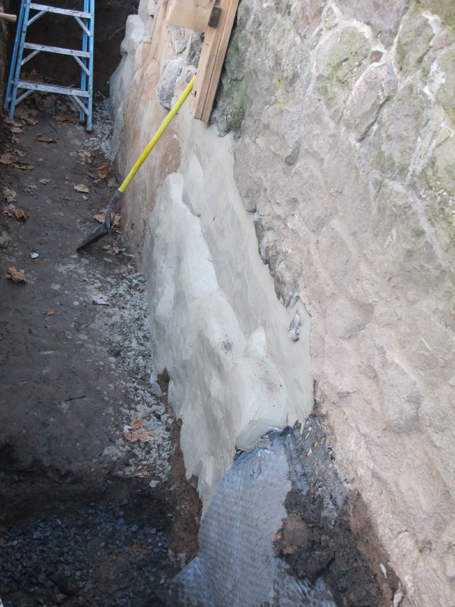
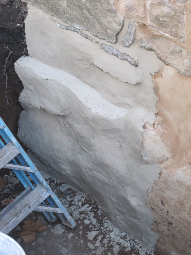
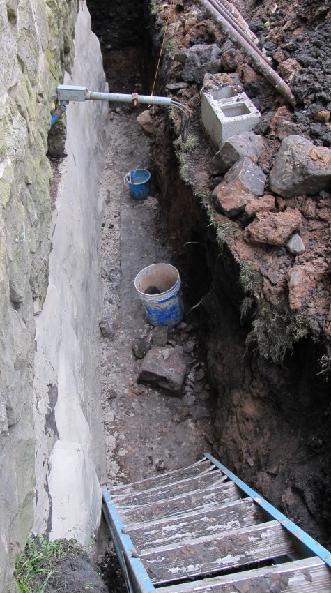
This series of 48 digital photos shows the restoration of the east eaves wall and other sub-grade foundation ranges. The lateral soils-bed was excavated along each foundation range to inspect and determine whether the foundation appeared to be more stable than the degraded foundation of the open cellar north of the transverse wall because of the buttressing effect from the fill materials inside the foundation enclosure below the concrete-capped crawl-space.
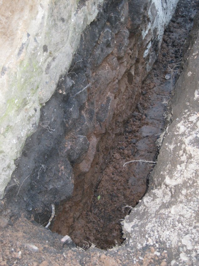
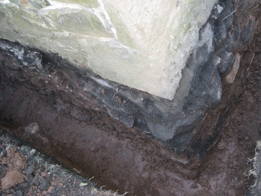
It became obvious that most of the foundation, although more regular in exterior plane and contour than the northern range, was nevertheless unsound because of the incoherent condition of much of the bed and joint mortar.
Based on these findings, most of the foundation supporting the entire structure would require reinforcement and stabilization. The remediation plan included:
(a) deeply and fully mortaring and back-pointing the beds and joints, filling all voids in the core and both wythes of the wall with mortar, and inserting small stones ["pins"] where necessary to reduce the volume of space occupied by mortar alone
(b) re-positioning displaced stone "units," generously applying mortar in-fill ["padding"] to all voids between them to inhibit lateral and rotational displacement or deflection of individual stones
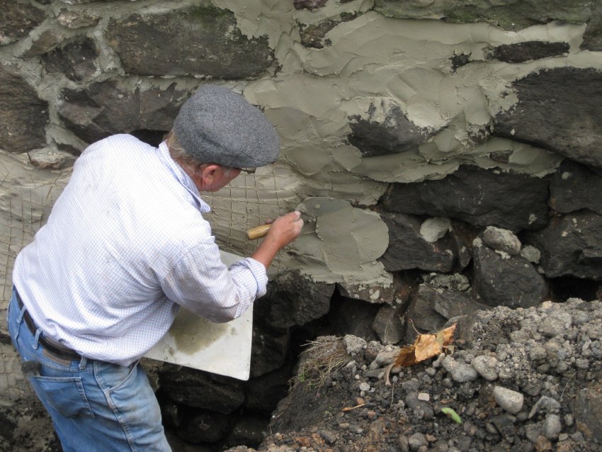
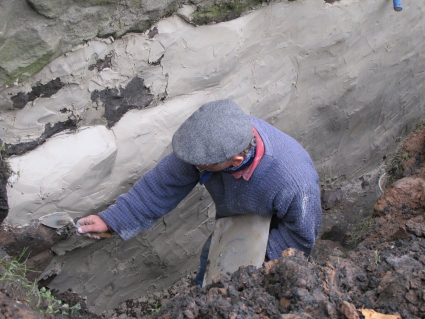
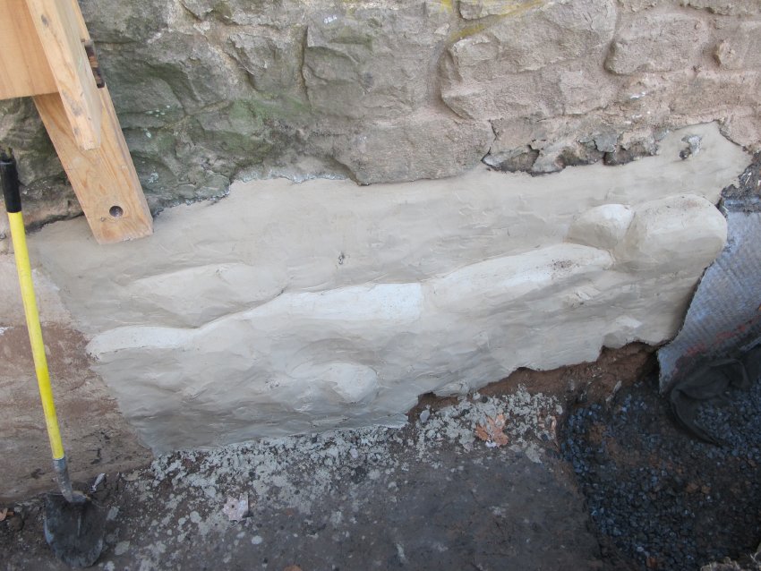
(c) application of built-up pargeting as a series of keyed "scratch" coats, gradually establishing a more regularly contoured exterior surface to accommodate the impervious membrane to be applied over the pargeting and waterproofing coating
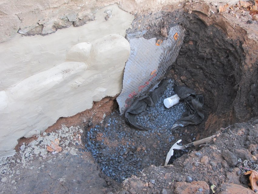
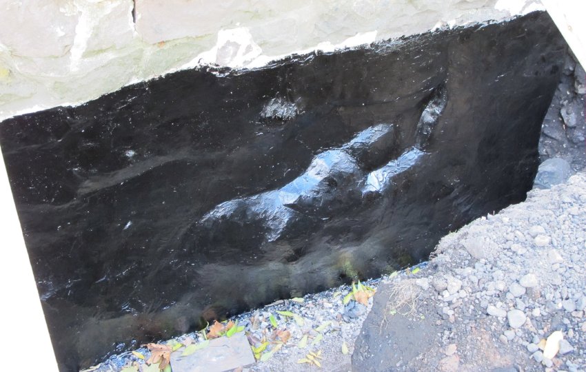
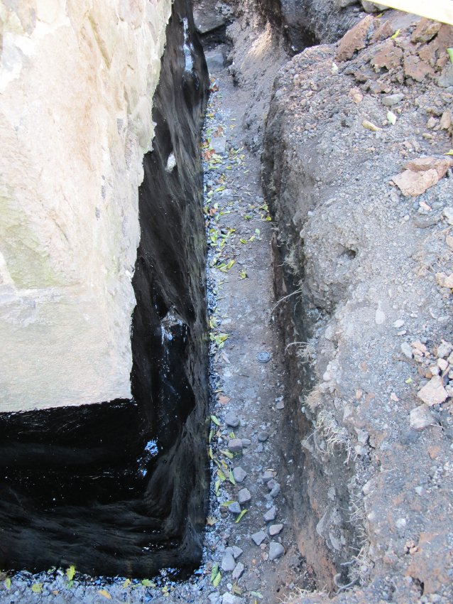
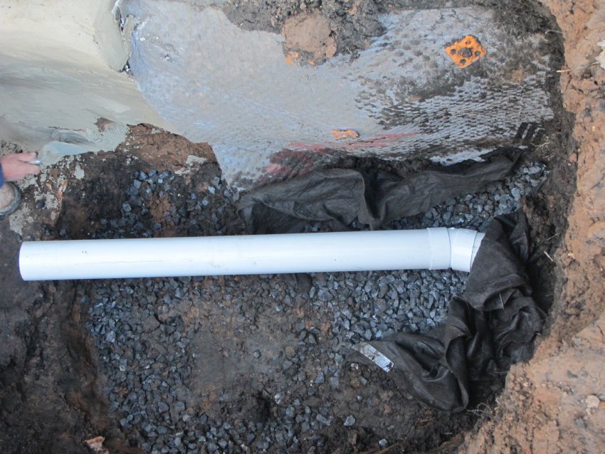
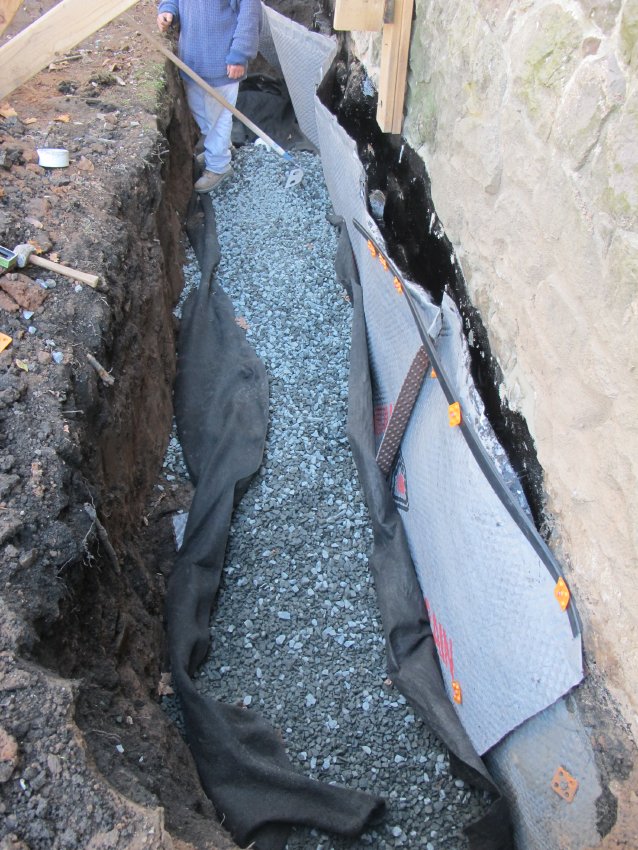
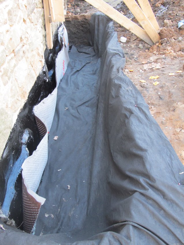
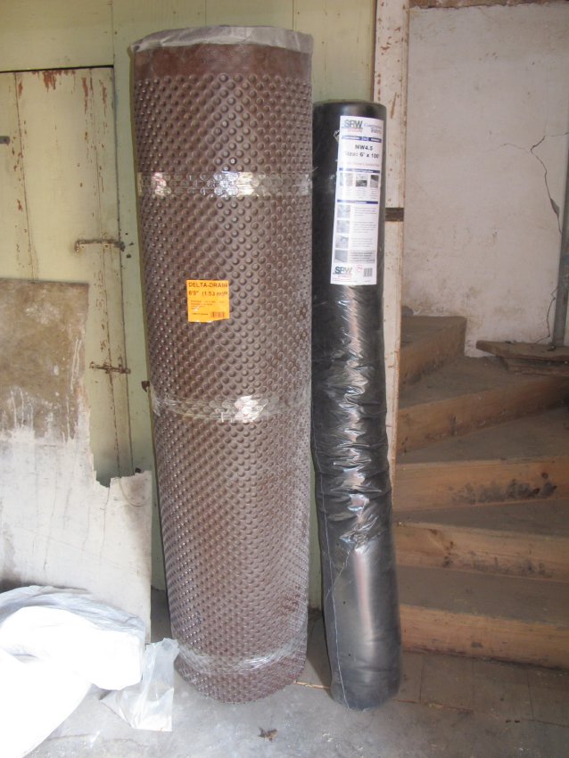
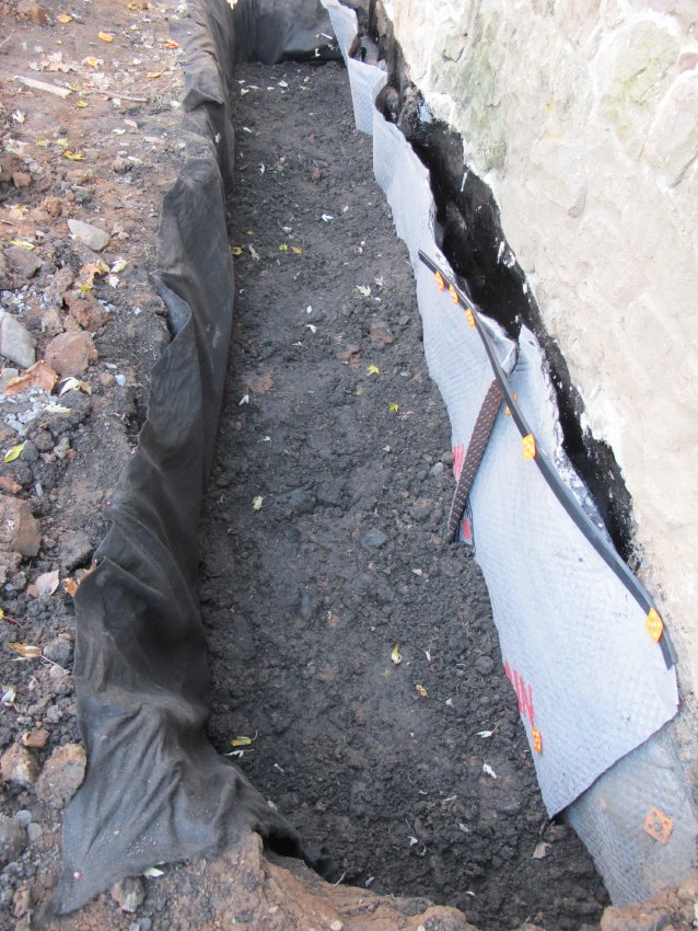
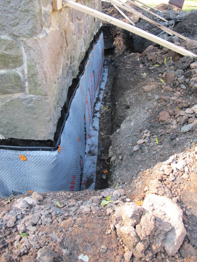
(d) two coats of a liquefied, rubber-based waterproofing material{1} and a flexible drainage board ["Delta Drain"] protected by a soil-filtering geo-textile fabric. This barrier will divert and conduct the moisture by gravity through the dimpled space between the filter fabric and the impervious sheet lining the wall, through a stone drainage bed wrapped with a geotextile fabric, then into a perforated PVC collection pipe. The collected water is then drained through a sloped, solid discharge pipe to an outlet protected by a backflow ["check"] valve.
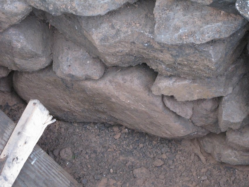
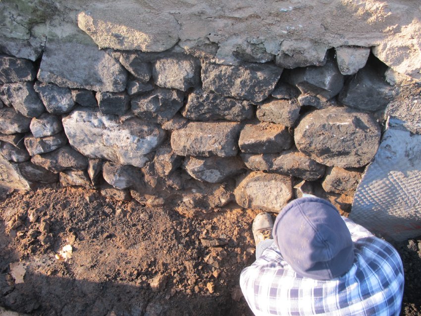
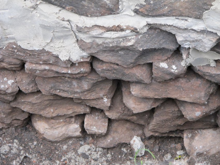
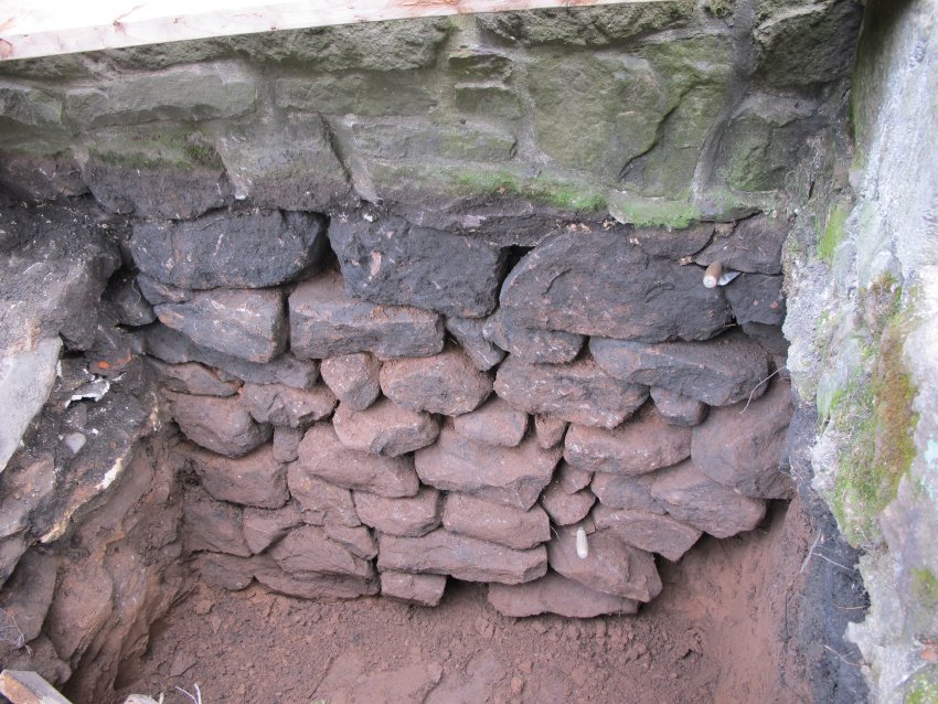
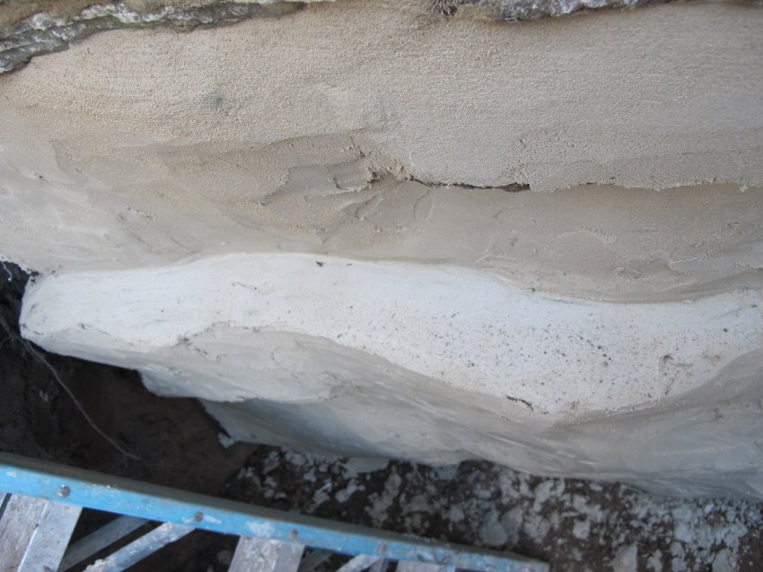
The larger stone across the middle of image #413 is a base stone, locating the bottom of the foundation in this range, approximately four feet below exterior grade and 6-8 inches higher than the bearing plane of the foundation and enclosing the cellar cavity under the northern half of the building.
DETAILED CAPTIONS:
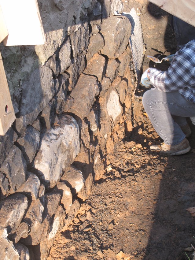
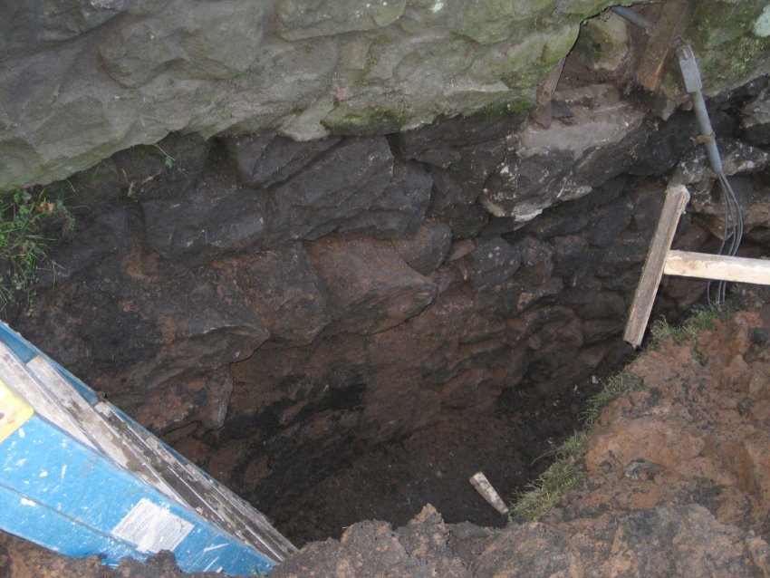
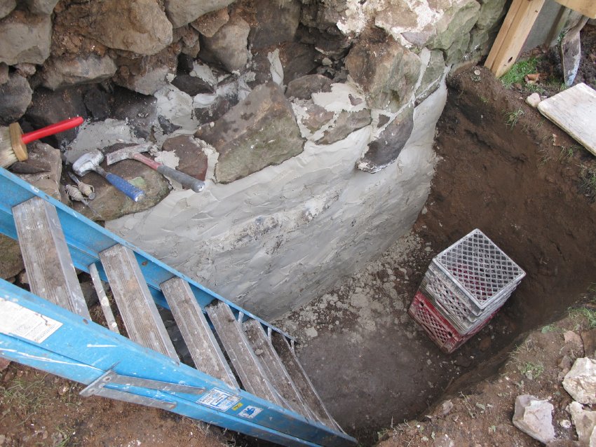
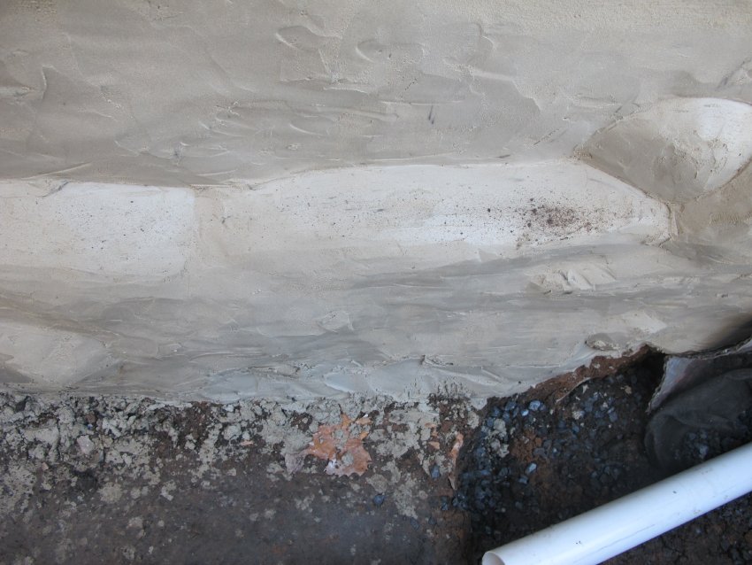
#406: Excavated sub-grade foundation below the delaminated grade-to-eaves wall segment under repair. No mortar or other bonding material remained in the beds or joints in the core of the wall. The reddish-brown residue in these photos is disintegrated lime mortar, sandy clay, and lime chunks. This friable residual material fell out, or was easily brushed out, of the wall. The marginal stability and unreliable bearing quality of this masonry depended on its thickness, wider at its base up to the top of the plinth, and a tenuous structural equilibrium within the walling, rather than on a well-bonded wall system. Other photos of unstable wall segments include:
#1192 & #1227 [exposed foundation ranges on clay sub-base]; #1237 & #1238 [details at northeast corner with stone "pins" and "plugs" being inserted]; #1249 [pre-restoration view of northern segment of east eaves wall showing large stones ["quoins"] of corner pier above and below grade elevation]; and 1286 [mid-range of east eaves wall foundation].
#407: Sub-grade detail of image #406.
#413: Detail of base stones set on bearing bed of compressed clay.
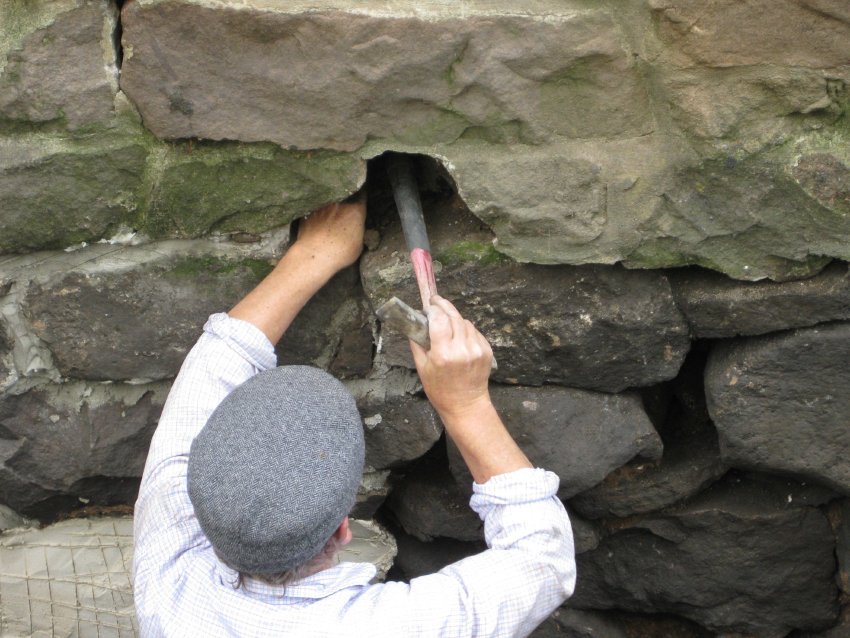
#736 & #744, 11/8/10: Raking disintegrated "mortar" residue from exterior joints. The projecting stone courses, ranging from 2-4 inches from the rough wall-plane, functions as a footing [traditionally "plinth"], demonstrating that the early builders were aware of the benefits of spreading the loads imposed by the structure over as great an area of bearing clay as is practicable. This wider sub-base "footprint" technique was not employed under the foundation of the cellar walls, partly because of the lack of the massive weight{a} imposed on the foundation masonry under the southeast corner of the building. The vertical boards shimmed against the wall act as a braced-buttress ["raking shore"] restraining movement of the wall at the margins of the unstable masonry during the dismantling and re-construction process.
{a} several tons per square foot or more under the fireplace and chimney stack.
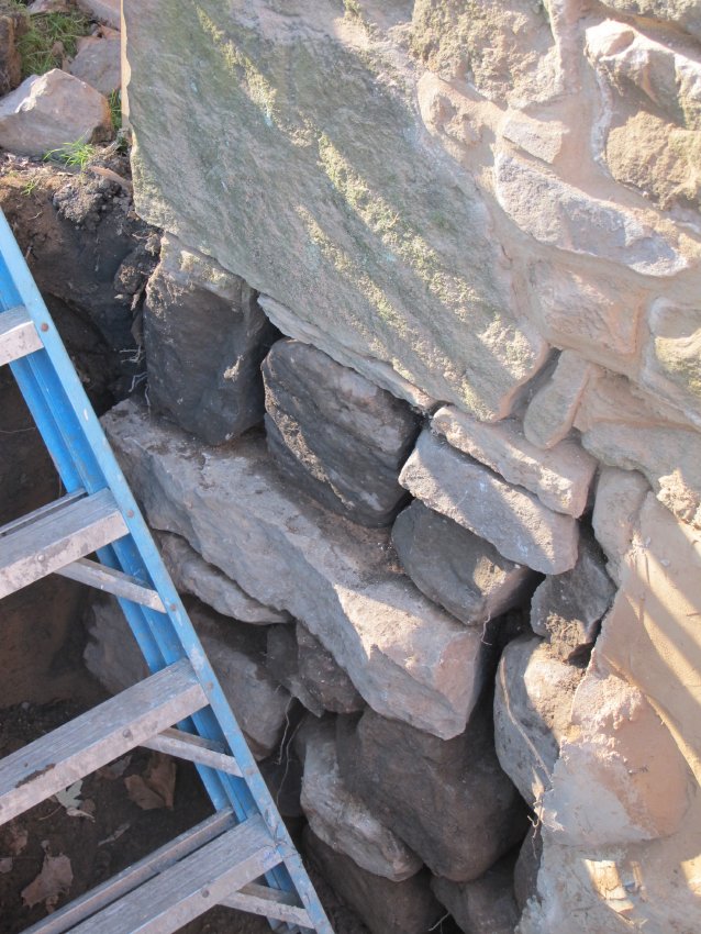
#789 & #1248 [10/20/10]: Raked-out and brushed joints of foundation at southeast "quoin" corner pier, prepared for deep-pointing and insertion of stone "pins" in larger voids before mortaring.
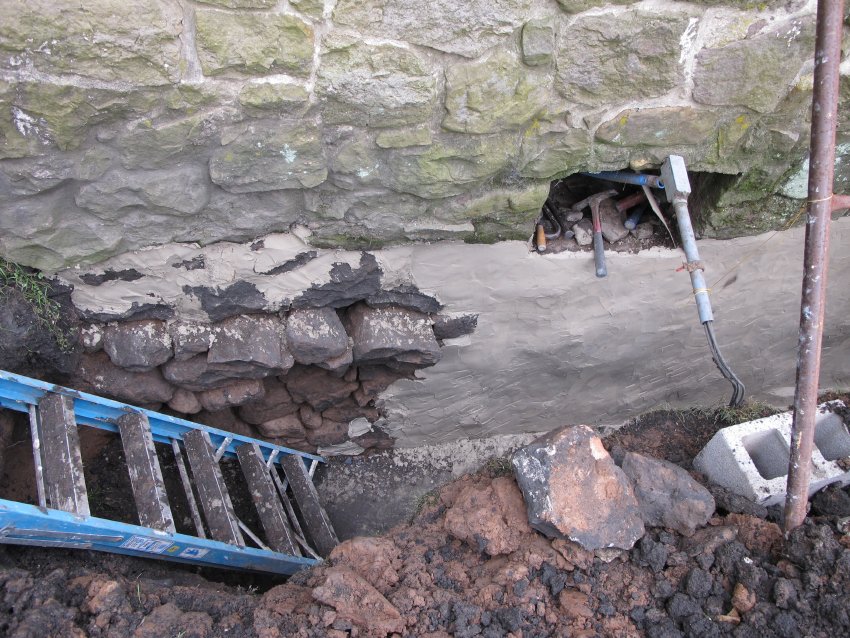
#1251, 10/11/10: Mason applying "scratch coat" of pargeting, "keyed" with incisions to form a bonded adhesion with the top ["finish"] coat.
#24, 10/18/10: detail showing voids in beds and joints of foundation, partially flush-pointed preparatory to pargeting.
#28, 10/19/10: base of foundation plinth of the southern segment of east eaves wall, with flush-pointing.
#46, 10/19/10: base and plinth in northern range of east foundation with mortar-packed joints and beds.
#48, 10/20/10: raked & swept joints & bed voids of foundation segment between cellar entry and steps to first floor in west eaves wall.
#1286, 10/15/10: raked-out foundation near SE corner of east eaves wall.
#52 & #58, 10/20/10: same section as in #48, packed and pargeted.
#1280, 10/14/10: NE corner of sub-grade foundation partially pargeted; note large de-stabilizing voids in joints.
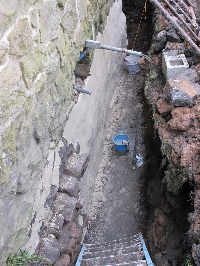
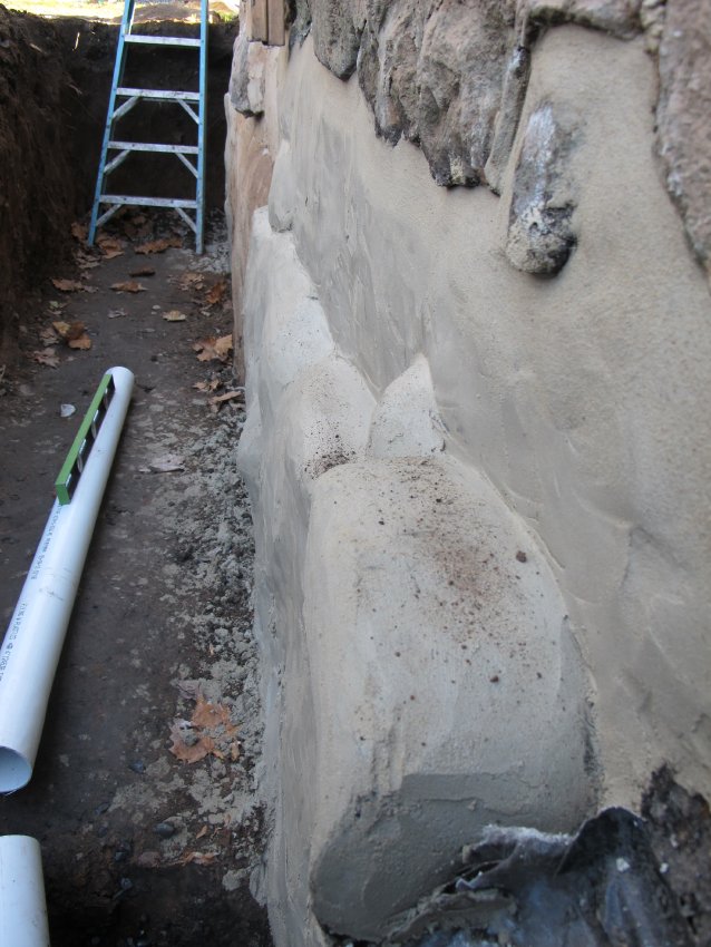
#794, #795, & #73, 10/20/10: mortar parge-coat over deep-pointed and stabilized 16-foot section of the east foundation.
#68, 10/20/10: Mason pargeting sub-grade foundation of east eaves wall after deep-pointing.
#796: Parged foundation range immediately south of center of wall. Lower-right corner of photo shows grade change of foundation; the clay below the coating will be "ramped" with tamped clay to impede and redirect water into the stone collection bed. Without this ramp, the water could scour and undermine the bearing clay base under the foundation.
#428, 10/28/10: detail of parged foundation segment in southern half of east eaves wall.
#797: Detail of #796 and capped perforated PVC pipe to which the piping from the southern collection system along this wall will be glue-joined.
#807, #811 & #815: Segments of parged corner pier, detail of foundation, and [#815] full length of 16-foot parged section to southeast corner pier.
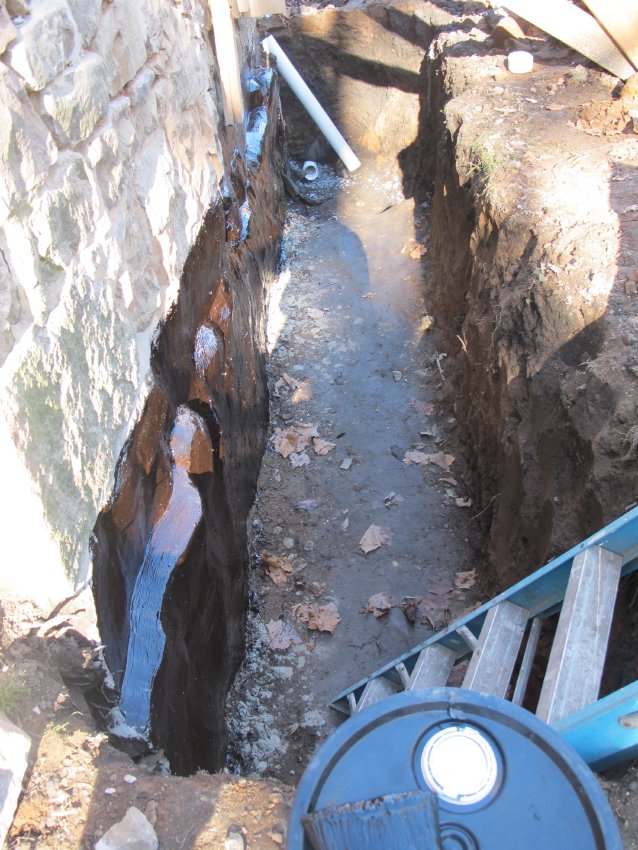
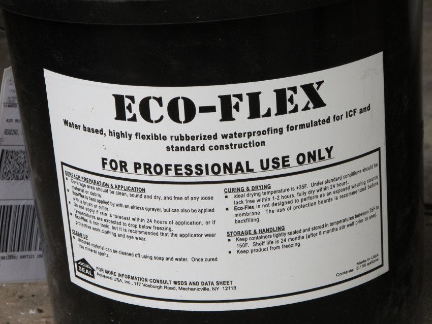
#105 & #107, 10/22/10: Water- and rubber-based waterproofing coating ["Eco-Flex"].
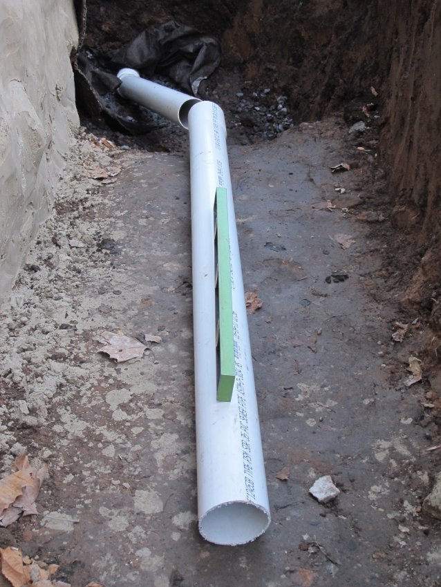
#801: Solid PVC pipe to conduct water from collection piping at higher foundation base to lower level perforated pipes along cellar foundation.
#805: setting minimal pitch in perforated collection piping.
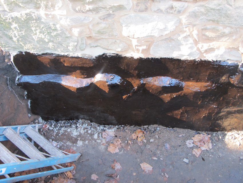
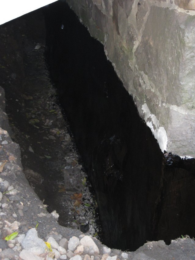
#821, #824, #825 & #1293, 10/17/10: Foundation after two coats of liquid rubberized waterproof coating [proprietary name "Eco-Flex", photo #61]. Brown sheen in #825 indicates material has not dried sufficiently for second coat. #1293 shows NE corner.
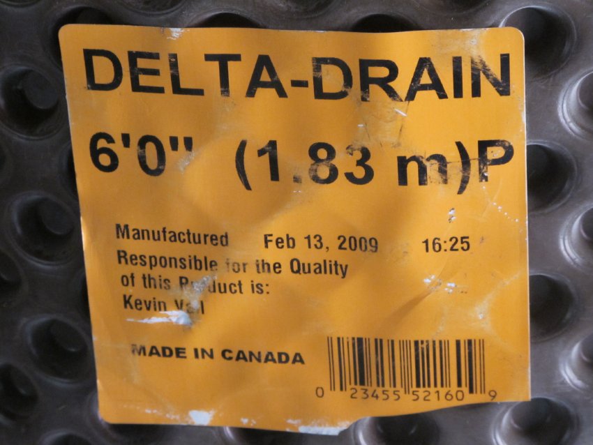
#847: Stone collection bed and drainage board [proprietary name "Delta Drain"; label photo #661, 11/6/10] set in position against parged and coated foundation. Drainage board will be fastened to coated pargeing with adhesive, and tacked through plastic "washers." A flashing strip will be applied across the top edge to deflect water onto the geotextile and through the drainage plane into the collection pipes.
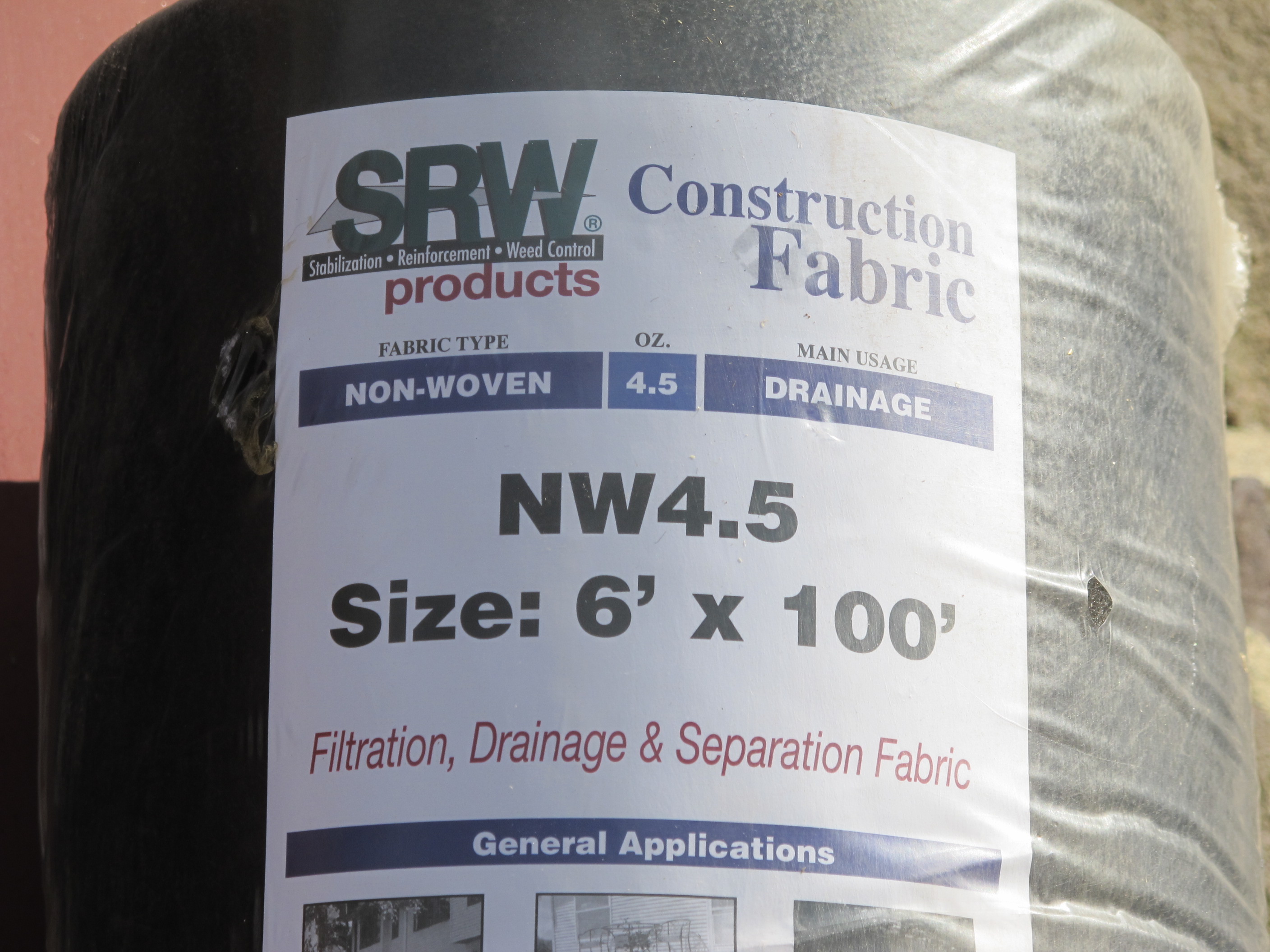
#848: Non-woven geotextile drainage fabric [4.5 oz. gauge, label photo #660, 11/6/10] wrapped around stone bed to filter out suspended particles in the saturated soils. Excess fabric will be cut away to avoid clogging. Photo #664, 11/6/10 shows fabric and moisture barrier/drainage conductor.
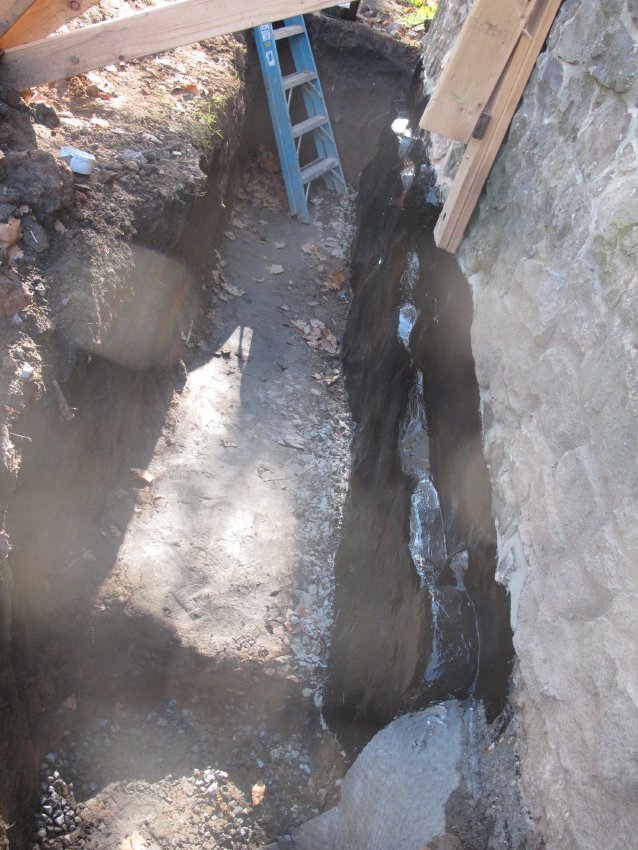
#884: Foundation excavation after pargeing sub-grade foundation, application of waterproof coating and drainage board [photo #190, 10/23/10], setting perforated pvc pipe in a stone bed, partially back-filled with well-draining soils. The clay removed from this excavation was not returned to the foundation fill because of the demonstrated risk of conducting water "perched" on the impervious clay beds to the foundation, compromising the integrity of the foundation by dissolving the lime component [the primary bonding agent] of the mortar.
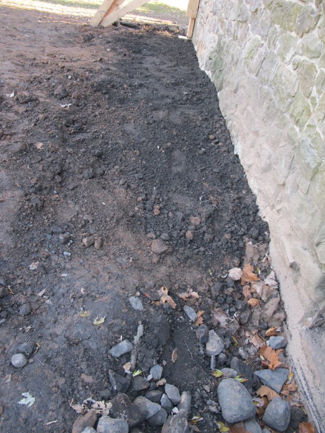
#909: Foundation backfilled to rough final grade. After settlement stabilizes, the grade along the walls will be slightly ramped downward away from the walls to conduct roof runoff away from the foundation{2}. Because of the dual-waterproofing applications to the foundation, and the sub-grade collection and drainage systems described above, potential long-term erosion from absorbed ground water will be postponed for many decades. Although not a 100% efficient shield against all destructive effects of water, this redundant set of moisture barriers and diversion facilities will provide exponentially greater protection to the structurally enhanced foundation stonework than the open joints of the masonry provided for over two centuries.
FOOTNOTES
{1} Proprietary name: "Eco-Flex," [label in photo #61, 10/20/10] which, according to the manufacturer Aquaseal USA, Inc., is a water-based, cold-applied, liquefied, waterproof, monolithic membrane, solvent-free, non-flammable material which covers approximately 200-250 square feet of masonry surface [two coats], yielding a nominal thickness of 40 mils [thousandths of an inch]. Although more expensive per gallon than bitumen-based products, the effective coverage per gallon is close to twice that of traditional "waterproofing" coatings, and should function efficiently significantly longer than such older and less "green" alternatives.
{2} Because of the protective systems installed below grade, capturing and diverting runoff at the eaves level or at grade surface are not nearly as critical as would be the case in the absence of these systems.
Larry Ward
Catalog details
- Catalog number
- 1005.01.059
- Alternate number
- MFHPH55
- Accession number
- 1005.01
- Date
- 2009 & 2010
- Creator
- Ward, Laurence
- Object name
- Print, Photographic
- Record type
- Standard
- Classification
- Documentary Artifact