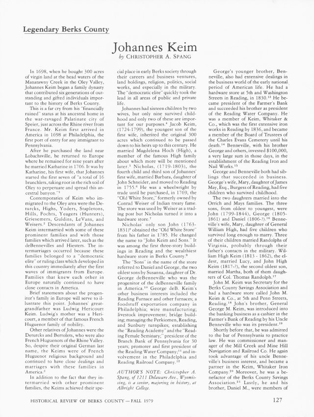
Three-page of article titled "Johannes Keim" by christopher A. Spang appearing in the Fall 1979 (Volume XLIV, No. 4) issue of "Historical Review of Berks County," a quarterly publication of the Historical Society of Berks County.
Article gives a brief history of Johannes Keim (starting in 1698) and key descendants ending in the mid 19th century. Topics disccussed include various Keim business dealings, land holdings (including the Keim Farmstead), religious activities, and military service.
See additional images or MULTIMEDIA LINKS for complete text.
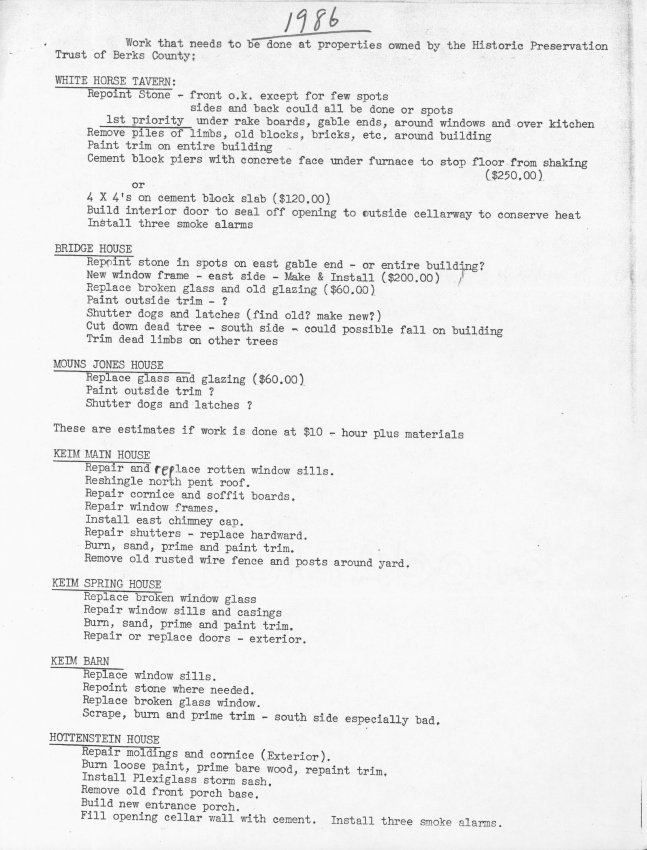
One page report outlining restoration work (and cost estimates) that needs to be completed on the following buildings: White Horse Tavern, Bridge Keeper's House, Mouns Jones House, Keim House, Keim Spring House, Keim Barn, and Hottenstein House.
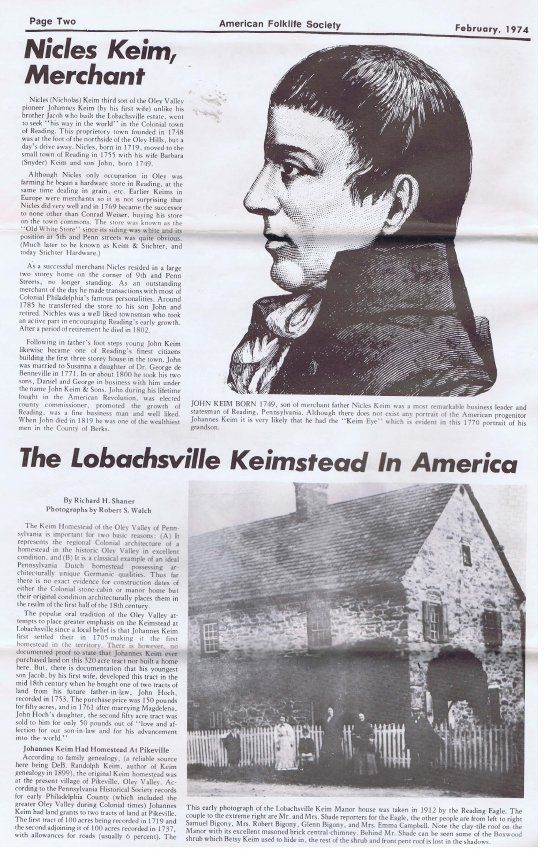
Three-pages of short articles from Volume II, No. 5 (February , 1974) issue of "American Folklife," a monthly newspaper devoted to the American culture published by the American Folklife Society.
First article, appearing entirely on page 2 and titled "Nicles Keim, Merchant," gives a brief history of Nicles Keim, third son of John Keim by his first wife and older brother to Jacob Keim who established the Keim Farmstead in Lobachsville.
Second article, beginning on page two & ending on page three is entitled "The Lobachsville Keimstead in America" was written by Richard Shaner with photos by Robert Walch. This article presents a brief history of the Keim family as well as evidence supporting the fact that Jacob Keim (NOT John) established the farmstead at Lobachsville. Also presents evidence that John settled near Pikeville.
Third article (with photos), appearing entirely on page four and titled "Folklife Plans," features information about the American folklife Society's restoration of the Keim Farmstead buildings, mainly the house and the cabin. Subjects briefly discussed include returing a later modified doorway into a window opening as well as the discovery of colonial brick flooring.
See additional images or MULTIMEDIA LINKS for complete images of pages two, three, and four.
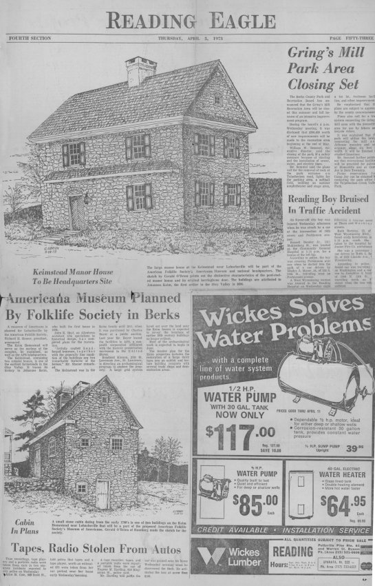
Half-page article with drawings (by Gerald O'Brien) from the Thursday April 5, 1973 edition of the "Reading Eagle." Article appears on page 53, Fourth Section.
Article briefly discusses American Folklife Society's (owner of Keim farmstead in 1973) plans for converting the Keim farmstead into a history museum & national headquarters site.
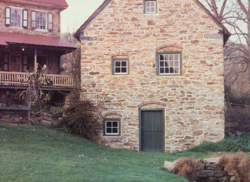
Color photographic print showing detail of the south elevation view of the Keim ancillary building. Note that the eastern range of the Keim Federal era addition to the 1753 house and 1930s porch can be seen in the left of this photo.
Details include: brick segmental relieving arch; 19th-century paneled shutters above porch
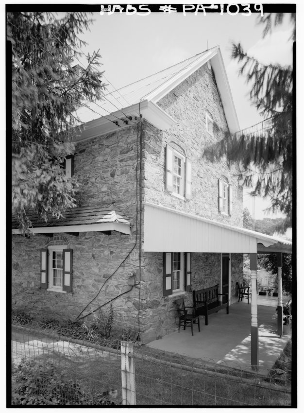
Northwest perspective view of the c. 1753 Jacob Keim house from Historic American Buildings Survey Photograph.
Description:
This view from photo, HABS PA #1039, shows: the pent roof on its original cantilevered “outlooker” supports on the northern eaves wall, with projecting “flashing course” protecting joint between shingles and house-wall [left]; the gable end segment of the 1930s roofed porch [right]; box cornice replacement of early plastered cove cornice; and brick relieving arches above windows.
Laurence Ward, February, 2021
Seven-page article (with photographs) appearing on pages 2-8 in the Fall 1975 (volume IV, Number 1) issue of "American Folklife," journal of the American Folklife Society. Article titled "Colonial Dressed Stone Structures" discusses dressed stone houses, V-pointing & flat pointing, brick arches & dressed stone, etc.
Approximately half of the article uses four separate current Trust properties as examples of dressed stone structures: DeTurk House, Keim Cabin, White Horse Tavern, and Douglass Mansion. Other buildings used as examples are the LeVan Manor House, Cook Mansion, Kaufman Manor House.
See additional images or MULTIMEDIA LINKS for full text.
Color photographic print showing details of the south elevation view of the Keim House and southwest gable wall of ancillary structure.
Details include: brick relieving arch, chevron door, portion of 1930s porch.
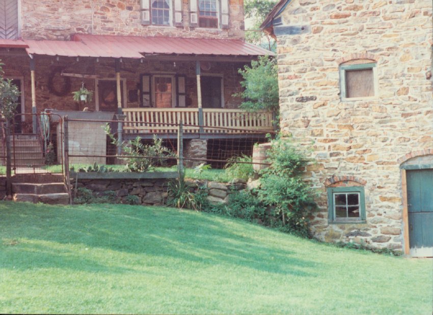
Color photographic print showing detail of the south elevation view of the Keim House. Note that portions of the Keim Cabin, Keim Barn, and Keim Outhouse (right) can be seen in this photo.
Details include: chevron door, brick relieving arch, 1930s porch.
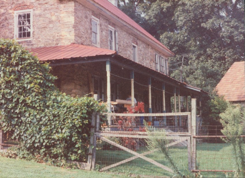
Color photographic print showing detail of a southwest perspective view of the Keim House. Note that the re-tiled roof of the Keim ancillary building can be seen along the right margin of the photo.
Details include: 1930s porch on south eaves wall and west gable wall, both grossly distorting the original proportions, massing, fenestration, and concealing period Germanic details of the 1753 house in rare combination. See record KR11PH3 for the rationale and preservation principles considered in removing the 1930s porch in 2011.
Updated, Laurence Ward, February, 2021
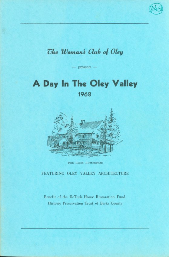
Ten-page booklet (6" w x 9" h) outlining a driving tour of the Oley Valley arranged by The Woman's Club of Oley.
Features include: map, one-page introduction, brief histories for seven sites, and acknowledgements of property owners and tour committee members.
The Keim Homestead is the second site featured. Brief historical text for Keim Homestead begins on page 4.
Full text of bookelt can be found under additional images or MULITIMEDIA LINKS.
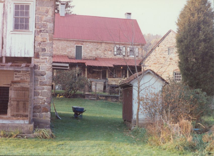
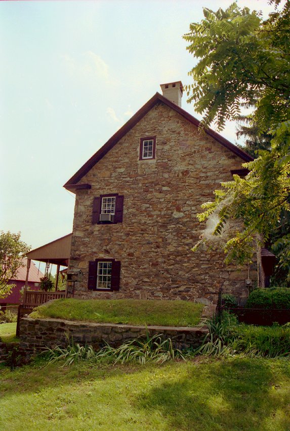
Frame # 15 of 16 (2-17) from 35mm color negatives, all various views of the buildings on the Jacob Keim Farmstead.
East gable elevation of Keim house with 20th-century Victorian-style porch on south eaves wall [left edge of photo], capped and parged chimney, and alternating "quoin" stone corner pier. This gable wall terminates the early addition to the 18th century farmhouse. In the mid-foreground is an arched and sod-covered root cellar, [aka a “ground cellar], formerly beneath a small gabled structure shown in an 1897 photograph and now protected by a roof with sloped doors for exhibiting the vault’s exterior [“extrados”].
Laurence Ward, updated March 2021
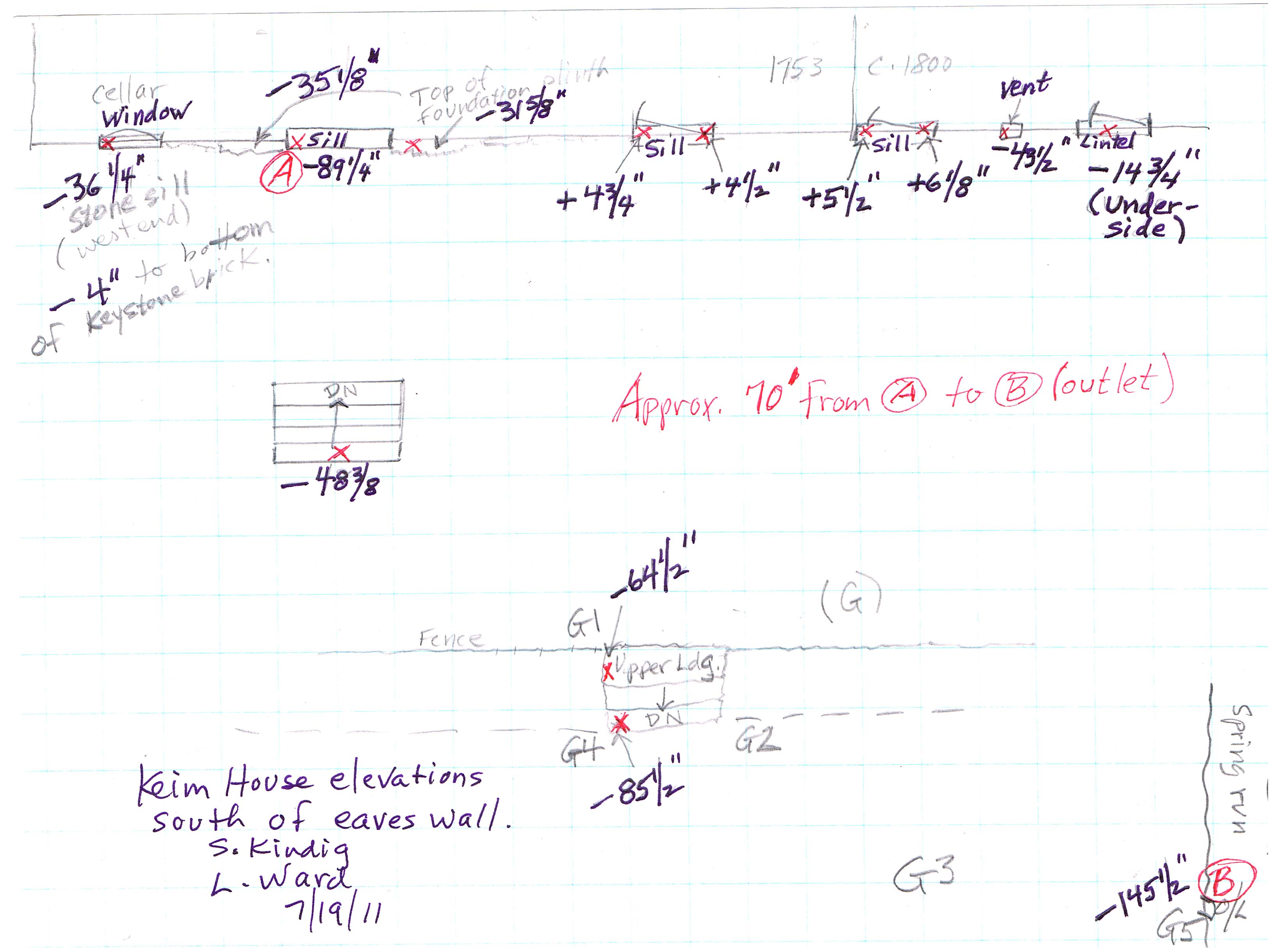
Keim House, field notes drawing, elevations South of the Southern eaves wall (2011). Digital image #1 is a Field Notes drawing showing the Keim House grade elevations south of the south eaves wall.
Description:
The data recorded on this sketch [together with future archaeological investigations] will provide guidance for determining the early and restored objective grades of the terraced yard area bounded by the 1753 house, the c.1800 addition, the mid-18th century "ancillary" wood-turner's shop building, and the low stone retaining wall separating the yard from the grass area north of the barn. The resulting data, in conjunction with soils strata and the degree of their disturbance, will possibly aid in determining the relative pre-and post-construction grades and the existence or non-existence of masonry supports for early entry structures at the 1753 and federal-era doorways. No such foundation remnants have been discovered as of 2015. This information will also facilitate the planning for surface drainage to be controlled by the final slopes, swales, and contours established for the terraced ground area and the contiguous inclined grade to the barn. Under early tradition and Common Law, these living and work areas adjacent to the house and principal dependency buildings have been called the "curtilage", and have been endowed with a privacy aspect for the occupants.
The wall and stone steps leading from the terrace to the barnyard were probably created in the 2d quarter of the 20th century (prior to the 1941 HABS photo in these archives), contemporaneously with construction of the two-wall porch that is depicted in archive record KHPH9--1002.01.044. Image #2, a photo taken c. 1929-1931 by Amandus D. Moyer, confirms the absence of a porch structure on the western gable wall as of the photo's date. The Moyer photo provides some indication of the early 20th century grades and slopes.
The early grade along the building is delineated by the top of the foundation plinth{1} which was concealed during the past century by the stone piers supporting the porches and the overfill of incoherent soils and small stones under the c.1930s porch (removed in 2011).
A stratum of dark top-soil a few feet below the present grade (which aligns with the top of the plinth) indicates that the post-construction (1753) grade was probably established by depositing sandy clay, probably excavated from the cellar space or from elsewhere on the farm, on top of the pre-construction topsoil.
The drawing in this record provides the plinth elevations on each side of the cellar entry opening [the east plinth is about 3.5 inches higher than the west]. These levels and the depth ["invert"] of the cellar doorway sill were the benchmarks which provided the relative elevations of the reconstructed stone retaining walls flanking the "cellarway" consisting of the stone steps and passage through the foundation wall [see record # KR11PH1].
The elevations recorded on the drawing and the point-to-point dimensions noted also indicate the appropriate pitch and run of the swales, contours, and topography of the surface drainage courses from the foundation, the roof runoff drip-line, and the perimeter-line of the retaining walls. All these grade contours are sloped toward the absorption area north of the barn and the margins of the spring-run south of the "ancillary" wood-turner's workshop building [see photos in record KR11PH2--1002.01.088]. These data could also provide a rational basis for future re-establishment of a close approximation of the grades south of the early farmstead buildings.
The elevation data also provided a mathematical framework for the constructive geometry and dimensions of the "cellar-cap" door and frame which would have spanned the retaining walls and sheltered the cellarway{2} passage; see archive record KR11PH1--1002.01.087 for commentary and photographs describing the reconstructed cellar entry-way, the probable form of early "cellar doors" [see the 1786 Rules of Work of the Carpenters' Company of the City and County of Philadelphia] which sheltered this opening, and the hypothesized "bulkhead" framing and sides ["cheek-walls"] which supported the angled and "hung-double" doors{3}.
The re-created retaining walls serve the dual functions of bearing the cellar doors and their support structure, and restraining the lateral soils and hydrostatic pressure from intruding into and jeopardizing the stairwell.
FOOTNOTES
{1} The base-wall ["footing", in modern terms; "basement" in neo-classical terminology] projecting beyond the plane of the wall it supports. This foundation segment, coarser in its irregular exterior plane than the "random rubble" contours of the above-grade walling, delineates the below-grade portion of the foundation. The plinth is thicker than the upper wall ranges, providing a structurally advantageous "basement" [the structural masonry perimeter supporting the building's superstructure and enclosing the cellar], and is not laid with a plumb face-plane or finish pointing, since it was not expected to be seen. It is quite possible that this segment of the foundation walls was laid from inside the cellar excavation, eliminating the need for pointing the exterior face of the plinth. The durability of the walling thus depended on "deep-pointing" the beds and joints from the interior of the cellar, rather than the more common practice of bedding and bonding ("mudding-in") the foundation stonework from both sides of the foundation, and often laying-up the exterior walls from a "builder's trench." Assuming that the base-stones are footed on a solid bearing sub-strate [on the Keim site, a dense amber-colored clay], both construction techniques provide a stable bearing system to carry the compressive load imposed by the massive super-structure of the masonry and timber-framed 1753 dwelling.
The top ["coping" or "water table"] of the plinth descends from west to east, delineating the final desired grade established as described above, and disappears as the grade along the wall falls toward the stone sill below the cellar doorway in the Federal-period addition. See the top of the "rubble" plinth in Image #3 [flanking the cellar doorway opening].
{2} Although a door could have been fastened to the interior abutments of the arched opening with pintles ["hooks", in 18th century terminology], no evidence has yet been found "documenting" a door frame attached to the arched masonry opening or joined to the joisted framing system above the cellar cavity enclosed by the basement. This suggests that no vertical door was present in the early period, which would further indicate the possibility of an "open-way" through the arched passage into the cellar. A door would obviously have provided a barrier of much smaller surface area than a "cellar cap" [the early term for the 19th-century "bulkhead" label] alone for the convection of heat out of the cellar in winter and into it in summer. A door and a cap would obviously provide a more effective thermal barrier than either alone.
{3} The raking bulkhead walls at the cellar entry on the northeast eaves wall of the c. 1762 White Horse Inn in Douglassville appear to be integrated with the foundation walls abutting the opening in a similar manner to the hypothesized bonded joint which probably originally tied the Keim cellarway retaining walls to the foundation plinth.
Laurence Ward, April, 2016 and updated January, 2021
Digital photograph showing view of east segment of south gable wall, showing some of the mortar-joint cracks which will be repaired in the 2010 restoration project. Portions of this gable and the chimney rising through its center have become separated [“delaminated”] and unstable, partly because of the poor alignment of mortar joints. Further inspection and analysis will be conducted to determine which portions of the walls, if any, are original or early structures, and which were reconstructed after the 1970 partial collapse, documented in numerous photos in this archive. (For views of the condition of this south gable wall after the collapse, see MFHPH32--1005.01.033 [corner pier], MFHPH33--1005.01.034 [interior] and MFHPH36--1005.01.037 [NW interior perspective] and MFHPH39--1005.01.040 [2d image, showing the SE “quoin” corner pier standing intact through its full height to the eaves level] .) Better practice in early random rubble masonry would not place mortar joints in vertically contiguous alignment with other joints; the potential pathways for “radiating” fractures would have been interrupted [“broken”] by placing stones, even without regular “coursing” in the wall pattern, between pairs of joints. Other somewhat redundant means of “breaking the joints” included embedding a timber “plate”{1} in the wall at the eaves level of gable walls [see DeTurk House photos DTR09PH93--1001.01.185, DTR09PH94--1001.01.186 & DTR09PH100--1001.01.192 and Keim Cabin photo KCPH1--1002.01.002 for examples of these short timbers “tying” one element of these early structures (the wall plate) to another (the masonry mass of the gable), utilizing the compressive forces of the masonry to bind the vertical joints they bear on and offset a portion of the lateral thrust on the wall plate ] and using longer stones, in compression, at critical locations in the wall to create structural separation between vertical joints, which might otherwise be connected, and thus create an “unbroken” pathway for cracks along relatively short (roughly) horizontal joints. These redundancies were lacking, or (regarding stone size and strategic placement) ineffectively utilized, in the pre-collapse masonry walls of the Michael Fulp House.
FOOTNOTE
{1} Depending on the alignment of this embedded timber and its joint with the wall plate at the top of the eaves wall, these timbers also served as “ties,” meant to restrain the wall plate and the masonry wall it bears upon against lateral thrust from roof and framing loads.
Larry Ward, 2016
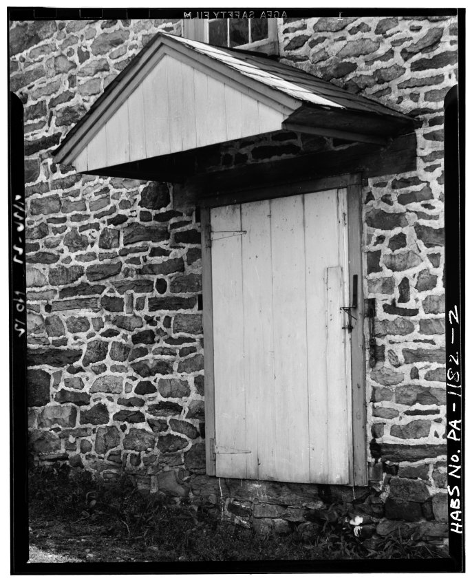
Digital image of Keim Barn from original photographic print showing gable-hooded doorway.
Details include: non-period door and hardware, gabled doorway hood.
Origianl HABS caption for the image is as follows:
"DETAIL VIEW OF HOODED DOOR."
Data sheets for HABS images (KBPH1--1002.01.029 & KBPH2--1002.01.030) associated with the Keim Barn appear in MULTIMEDIA LINKS or see Archive record KBTX1--1002.01.036.
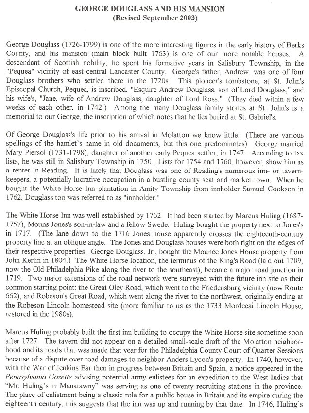
A six-page type-written history of George Douglass and his business influence in the area of current day Douglassville, PA, as well as a description of his political and business success. Text also contains various descriptions of elements of the George Douglass House, including the full-perimeter [“encircling”] plastered cove cornice, a refinement emanating from late 17th century “Baroque” English influences. This form of eaves transition appeared in Philadelphia in the very early 18th century, and within the next half-century migrated to Germantown, Chester and Montgomery counties, and eventually arose on more remote Germanic houses such as the Keim house in Berks County [see Archive record KHPH9 and the accompanying images and Footnotes].
See additional images for full text.
Larry Ward
Image #1 [photo #5579, 11/11/13] and the attached drawing dated 2/18/15, revised 3/12/15 [folder dated 4/14/15] show the two adjacent arch-form masonry vaults in the cellar of the 1765 George Douglass House against the below-grade foundation of the southern gable wall of the kitchen. Photo # 5773, 11/18/13 depicts the shared pier and triangular impost from which both vaults spring.
This illustrated record will discuss the historical origins, structural function, and laterally stabilizing relationship between this pair of classically conceived and mechanically integrated vaults.
Beams and Arches: The iconic Greek lintel, composed of stratified bearing and decorative elements forming a segmented entablature, is functionally a beam. A beam is supported only at its terminals, usually columns or wall sockets, often with no intermediate posts or other bearing points. The tensile stresses on a beam under load are well known, quite predictable, and critical in limiting the spans beams can reliably bridge. These essential mechanical principles accurately define the load-limits any beam can effectively and safely support.
An undersized or structurally deficient beam deflects, deforms, and ultimately fails under strains exceeding its tensile capacity. Beam integrity is determined primarily by the strength of the material of which it is composed and its vertical dimension, which is squared in determining its strength. Stone and similar earthen materials perform far better in compression than in tension. The axioms and calculations predicting timber-beam performance that early carpenters and joiners understood from practical experience, European “guild” training, and durable results are analogous to the stone mason’s instinctive “pocket guide” to arch and vault design and the acquired methodology expressed in their vernacular stonework.
However, the construction methods and risks related to designing and constructing masonry arches and vaults over long spans are exponentially more complex than those applicable to a level horizontal beam. Colonial and Federal vernacular masoning skills were implemented with minimal understanding of the mathematical formulas or mechanical principles governing arch and vault design adequate to resolve a wide variety of structural objectives. Despite these theoretical and technical deficiencies, continental and colonial masons achieved an admirable degree of competence in producing the complex and enduring curvilinear stonework erected in accordance with the ancient techniques and constructive sequences prescribed by the “art and mystery” of their trade. Once they learned which combinations of radial geometry values achieved durable results, masons in the back-country who “paid their dues” in the vernacular guild culture could confidently create the degree of stable consolidation of stone and mortar to produce functionally monolithic arches and vaults.
By contrast with a horizontal beam, structural arches are able to span wider dimensions because, properly formed, loaded, and buttressed, they counteract and “neutralize” all compressive, oblique, and tangential forces and stresses imposed on the voussoirs forming the arch-ring. This more complex set of force vectors in arched or vaulted systems creates significant horizontal and oblique thrusts acting on the piers, wall abutments, or other fixed mass supporting and laterally stabilizing the arch or vault. An arch more reliably supports loads to a greater degree than a lintel primarily because the arch converts a significant portion of the forces imposed upon it to a compressive [gravitational] vector supported by the earthen or paved stratum bearing its foundations. The gravitational (“compressive”), lateral, and oblique forces consolidated on the impost and its support structure are “taken to ground” or other “footing” base on which the entire mass is ultimately borne. Lateral stability depends on the abutments. The abutments constraining the fireplace support-vault include the smaller arch integrated to it and itself securely abutted by the eastern foundation wall.
The Drawing entitled “Arch Forces” shows with arrows a simplified analysis of the forces imposed on and supported by a masonry arch. The arrow labeled “R” [for “Resultant”] is a consolidated indication of the aggregate of forces generated by the arch and its loads as focused on the “Springers”; the two force “vectors” summarizing the compressive and lateral components of the resultant force are indicated by the arrows “VC” and “VL” respectively.
Arch Origins- The Roman Antecedents:Corbeled “tunnel” vaults with roughly converging apexes appeared in stone walls and passage structures in the middle-east nearly 2000 years ago. More mathematically complex and mechanically effective than the column-and-lintel systems prevalent in monumental Greek structures, masonry arches and “barrel” vaults, most composed of large bricks and mortar, flourished in classical Roman architecture and appeared in stone in cultures east of the Mediterranean Sea during the 500 years BCE. Some vaults intersected, forming groined (and later ribbed), quadripartite vault bays spanning the spacious naves of 10th century Romanesque churches, ceiling a magnificent multitude of even more voluminous Gothic Cathedrals displaying “pointed” arches during the medieval period, and roofing Romanesque and Renaissance cathedrals [cite JSAH].
The Renaissance and its Influence:The Italian Renaissance of the 15th through 17th centuries and its widespread architectural influence produced an abundance of semi-circular and segmental structural arches, little changed from the classical Roman and intervening Romanesque prototypes. The cult of the arch spread rapidly north of the Mediterranean. Large-scale radial arches provided structural integrity in hundreds of major building campaigns throughout the Germanic Principalities during the “Northern Renaissance.” The mechanical success of the Roman Empire’s enduring architectural and engineering achievements for nearly a millennium assured the primacy of the “round-form”{a} arch in structures erected within its vast area of political dominance and architectural influence. Arches and vaults{b} proved to be exponentially more effective than the column and beam [“trabeated”{c}] Greek forms in critical bearing functions in the classical world and all subsequent architecture influenced by it. The semi-circular, elliptical, and multi-radial arch forms spawned by Rome evolved little over the ages because of the structural success and stunning beauty of their prodigious lineage. The lithic DNA of the arch required few mutations to perpetuate its survival into its third millennium and for the foreseeable future.
{a} Generically of two types: (1) semi-circular arches with intrados and extrados tracing arcs with constant radii terminating at the horizontal chord connecting the imposts on the abutting piers; and (2) segmental or elliptical arches with radii converging at a center (or multiple centers) below the impost cord, tracing less than a half-circle or an eccentric arc from impost-to-impost. The various profiles and radial patterns in masonry arches are diagrammed in the “Masonry Arches“ drawing in this record, from the 3d edition of Architectural Graphic Standards by Ramsey and Sleeper (1941 and 1949).
{b} The traditional definition of a round-form vault is: a masonry arched structure with a length longer than its span between imposts. A functional definition, less focused on the dimensional proportions, would refer to the distinction between the typical passageway or arcade openings created by an arch compared to the essential bearing, ceiling, and enclosing purposes of a vault. The Douglass cellar vaults fall into the latter category, relegating the dimensional formula to a lesser significance.
{c} as distinguished from arch-form or “arcuated” systems, with voussoirs [the individual canted stone units forming the arch-ring] of appropriate geometry and sizing to provide reciprocal and monolithic stability crucial to supporting the incumbent load.
The English architectural renaissance:17th century British masons and architects produced and adapted to English design preferences an abundance of buildings derived from Roman [more proximately, northern Romanesque and Italian Renaissance] prototypes, adapting masonry passageways and bearing-arch forms to a variety of functions in vernacular and academic buildings. The architectural results included an impressive array of grand houses in Great Britain and robust symmetrical domestic buildings in the new villages and farmsteads structures in the New World. These American evolutes were often assimilated and adapted by collaboration and parallel development contemporaneously with continental influences and practices. The colonial vernacular expressions in masoned stone became more ingenuously refined and articulated.
The peripheral support elements abutting an arch or vault must be sufficient in mass and lateral integrity to neutralize the outward stresses generated by the arch or vault and the superincumbent loads borne by them. Not all of the gravitational load supported by arches and “barrel” vaults are “converted” to compressive gravitational loads and fully borne by the imposts [“I” on Drawing GDH vaults color] through the springers [“S” on Drawing GDH vaults color] and borne by the piers or wall ranges abutting the arched span. Arches and radial vaults depend on stable abutments as well as compressive gravitational bearing piers to fully restrain and counter all force vectors, particularly lateral forces, and superincumbent loads imposed and “acting”{d} on the arch. The ultimate durability of the finished structure is dependent on the quality of the wall-builder’s “laying-up” technique, most importantly the transverse bonding patterns conceived and implemented to compress and thus secure joints between stone units. The impressive result of the form and laying-up techniques producing these arches is masonry cohesion achieving a functionally monolithic stability.
{d} A misnomer, since the ambient loads and force vectors borne by an arch or vault are static [“dead”, not “live”], when in equilibrium. Properly designed arch-form bearing structures resist and neutralize live or “dynamic” loads and “charges”, as well as static burdens. However, this discussion will consider only the static aspects of arch-theory, since most Pennsylvania structural arches were built to such a redundant mass and scale that they easily absorb and dissipate the live loads periodically occuring.
Master masons designing and supervising stone building projects on the Continent and in the British Isles assiduously trained their corps of journeymen{e} and apprentices in the “art and mystery” of their trade. In the following centuries, including the 17th and 18th century era when William Penn was “planting” his vast American colony with immigrants and their craft-cultures, stone buildings (and many of brick in urban centers such as Philadelphia) began to appear throughout the settlement areas of Pennsylvania. Many masons, journeymen and “masters” working within a hierarchy of artisanship commensurate with their levels of spatial perception, acquired skill-set, and applied workmanship, emigrated to the American colonies, transplanting with them those prescribed and creative means and methods engrained in their individual and collective craft-memories and imprinted on the fabric of completed structures in which they were engaged. The Germanic form of the Romanesque arch crossed the Atlantic in the custody of a large corps of stone masons skilled in its use and capable of transmitting its traditions to fellow Germanic and non-Germanic artisans in the Atlantic colonies.
{e} The status of "journeymen" in the various construction trades in the English craft tradition designated someone who had completed his apprenticeship and was deemed qualified to "journey out" to construction sites to work within his craft for wages. In the continental Germanic Trade-Guild tradition, this was called “Wanderschaft Peregrination”, a one or two year journey to “ausland” regions and cultures designed to afford knowledge and experience in trade practices and techniques outside the apprentice’s home region, and to broaden the experience and skill-set of the “Handwerks-Bursch” [Traveling Journeyman] beyond the local methods and specialized techniques learned in his youth; cfr. Rush’s Account of the Germans in Pennsylvania, as published in the Proceedings of the Pennsylvania German Society, Vol. XIX, at page 50, especially Rupp’s footnote 23, ibid.
???????????Thousands of records of Indentures binding a large percentage of immigrants to work in Pennsylvania from 1771 to 1773 recite that the “Apprentice” or “Servant” was to be taught the “art, trade and mystery” of the designated occupational category; see records published on pages 1 to 325 of Pa German Society Proceedings, Vol. XVI (1907), in the essay entitled Record of Indentures of Individuals Bound Out as Apprentices, Servants, Etc. and of German and Other Redemptioners…October 3, 1771 to October 5, 1773.
Most of the Germanic immigrants settled and began working in Pennsylvania. The English artisans, trained during the 17th century “post-fire” building boom, also understood and utilized the structural arch, and possessed the requisite skills to produce enduring stone structures in the Atlantic seaboard “plantations” emerging in the colonial period. In southeastern Pennsylvania, masonry techniques and constructive protocols, informed by Continental and English practices and training requirements, found expression in a variety of structural applications in vernacular buildings crafted in the piedmont and burgeoning farmland settlements radiating out from Penn’s “Green Country Town”.
It is reasonably well documented that Germanic masons worked on Anglo-Pennsylvania [“Georgian”] houses in Germantown [1740s] and at Pottsgrove [c. 1752], and a few miles east in the George Douglass mansion [1765]. Farmstead buildings, Taverns, crossroads log and stone houses and their dependencies displayed arch-form doorway “heads”, segmental [“elliptical”] “relieving” arches spanning door and window openings, and durable vaults in cellars and ground-level stables designed and sized to support fireplaces and chimney stacks, wagon ramps, and to “ceil” “tunnel”- [barrel-] vaulted root cellars [also called “ground”{f} or “cave” cellars]. The work product derived from this craft history and tradition was durable and highly functional, and remains so where preserved.
{f} see Williams, David G., The Lower Jordan Valley Pennsylvania German Settlement, August, 1950, pp. 151-2 and following plates, observing that “Almost every farm of any size included one of the ground cellars among its buildings”, with arches “which vary from quite flat…to almost [semi-] circular…”
Vernacular Masonry: Early “back-country” masons possessed little or no knowledge of classical or Newtonian mechanical principles or the mathematical calculations{g} necessary to precisely calibrate the forces acting within an arch-form masonry structure. They lacked the formulas developed by solid geometry and force-vector analysis to design for massive (for many vernacular craftsmen, incalculable) loads, thrusts, and strains which burdened and imperiled the structural integrity of masonry buildings of the period. Instead, they marshalled their shared experience and honed their practical problem-solving insights and methods to rectify the inevitable failures as buildings in the region became larger and structurally more complex. Under the guidance and discipline of the most skilled among them, they managed to work-out and fabricate arches and vaults of sufficient mass and mechanically effectual form to support immense loads [measured in tons]. The transplanted “art & mystery” of the mason’s craft produced an impressive array of arched passage, bearing, and buttressing elements in a wide range of masonry applications.
{g} French mathematicians were working out the formulas and calculations governing arch performance, form, and size from the late 16th through succeeding centuries. It is doubtful that early European-American craftsman had access to or comprehension of the complexities and implications of these theories and the empirical refinements initiated and shaped by them. The architectonic results were formulaic guidelines determining voussoir shapes, weights and cant-angles, abutment pier dimensions, joint friction, impost design and placement, the orders of magnitude of compressive loads and lateral thrusts, and similar details and consequences produced by the finished structure.
Alternative bearing systems for fireplaces included coursed corbeled stonework, with each cantilevered layer of stones projecting out incrementally from the lower ranges embedded in the abutting walls, counteracting the compressive loads, lateral and oblique thrusts, and stresses from the fireplace hearth, jambs, and chimney stack borne by the inversely stepped support [Hunter-Shelley photo #4428, 4/13/15]. These support variants were less expensive and obtrusive, but could not bear the immense loads carried by well-constructed arch-form vaults.The ancient technique of laying arch-ring [“voussoir”] stones on temporary timber supports [called “centering” or “false work”] until the compressive and radial bonds between stone and mortar is sufficiently cured [“set up”] continues to the present day as the preferred method for constructing Roman-form arches and “barrel” vaults. This wooden form-work method was essentially the same in the mid-20th century as in arch structures produced in ancient and classical-revival periods, a span of more than two thousand years [see Shelley barn-arch photo, #1, 3/7/15].
The George Douglass House Cellar Vaults
The proposed replacement of the 1765 Douglass house kitchen door and frame in the gable recess next to the large cooking fireplace required the Trust to investigate and determine a plausible function for the narrow barrel vaulted structure [photo #5775, 11/18/13] in the southeast corner of the cellar under the doorway passage east of the fireplace jamb. Located adjacent to the fireplace support vault [photo #2613, 12/31/14] and directly below the gable-wall doorway passage adjacent to the kitchen fireplace, the corner vault might intuitively be expected to have been constructed as a bearing structure for a compressive load, possibly a bake oven. Inspection of the residual material and framing configuration under the floorboards should reveal whether any bed mortar or leveling course remains on the vault extrados as a bearing plane for a masonry structure which George Douglass hypothetically intended to install in the corner recess.
No significant masonry mass or other gravitational load is borne by the narrower vault, except for a minimal component of the eastern jamb of the fireplace above [ see GDH vaults Drawing dated 2/18/15 and revised 3/12/15], and there is no evidence that it ever did so. The space above the corner vault has been a joisted-floor passage to the gable doorway from an early period, and is probably an original plan detail. The framing, though since altered, is similar to the centered principal doorway framing in the western facade. Whether George Douglass realized the importance and benefit from this convenient passage belatedly, and consequently discarded the bake-oven element is an un-documented subject of conjecture.
It seems implausible that the gable-corner doorway was an afterthought brought to mind only after the masons had spent considerable time and material constructing two classic arch-form vaults and carefully designing the common pier supporting the shared triangular impost{h} and “springers” of both arches. Rather than speculating as to what purpose was intended for the corner vault, it seems more useful to recognize the structural function that is demonstrably served by it. As currently configured, the small vault is an ideal buttress for the large vault supporting the kitchen fireplace. The two vaults share the narrow pier as a common “jamb” and provide perfect lateral support for each other. The convergence of opposing force vectors from each vault, reciprocally neutralizing each set of stresses, creates stable equilibrium in both.
{h} The triangular stone centered on the pier between the vaults and bearing the springers of both vaults. As a consequence of the symmetrical and opposing force vectors focused on the angled faces of the impost through the springers of the two vaults, the mechanical effect is to stabilize the two-vault system at their joinder on the impost. There is no compelling evidence or constructive analysis that the smaller vault served, or was required to serve, any other structural purpose.
The following discussion will address only that function which the vault actually performs, not what its speculative purpose or other hypothetical intention, later presumably abandoned, might have been.
The gravitational loads and lateral thrusts imposed on arches are resolved and stabilized by the compressive strength of the arches and the redundant buttressing effects of the flanking structures (walls, piers, and adjacent integrated structures, such as the pier-wall from which the western end of the Douglass fireplace support vault springs, and corner vault formerly the support base for a corner fireplace, now removed) which abuts it. The combined mechanical effects achieve a coordinated condition of static equilibrium in the masonry masses borne and laterally stabilized by the well-crafted and buttressed vault system. The arch-ring and the pier-and-abutment elements that “clamp” it in place are equally indispensable in the creation of an enduring arched or vaulted work-product. The integrated pair of arched vaults bearing and stabilizing the Douglass kitchen fireplace has successfully manifested all essential functional criteria for two and a half centuries. It is not necessary to speculate about what Douglass might have had in mind about a bearing function for the small vault. It has served as the perfect buttress for the fireplace vault for nearly ten generations. In the absence of documentation or other compelling evidence in the architectural fabric, it cannot be asserted with certainty what the original purpose of the small vault might have been. We can, however, recognize the structural function it does unequivocally perform, namely to counter and neutralize the lateral and oblique thrusts imposed by the fireplace vault and the “superincumbent” loads it supports. Under this premise, the small vault is a mechanical buttress rather than a gravitational support in simple “compression” and bearing an intuitively imagined kitchen fixture.
The wider vault, nearly 12 feet in total length, shares an abutment pier with the smaller-vault, which also serves as a shared “jamb” [see photo Image #5773, 11/18/13 and the stone marked “P” in drawing dated 4/14/15]. The larger vault is a prime and enduring example of a masonry structure in stable equilibrium under the massive compressive load of the fireplace and three-story chimney stack borne by it. The smaller vault is (apart from any conjectural bearing role) an ingenious alternative to a massively redundant abutment pier which would have otherwise been necessary to provide the equivalent counter force against lateral thrust from the fireplace foundation vault [see drawing #GDHA3]. Together, the two-vault system produces a mechanically integrated and stable support system for the set of forces imposed upon and borne and neutralized by them. The drawing indicates that the shared vault pier performs its compressive function by supporting the fireplace jamb and chimney wall directly above it. It also supports the triangular impost stone which is the bed for the arch springers [“S” on GDH vaults Drawing dated 2/18/15 and revised 3/12/15] ranging through the full depth of each vault. Mechanically, this convergence of forces produces the equilibrium necessary for the long term durability of the incumbent loads bearing on the two vaults.
The Douglass house masons and the master housewright in charge of coordinating construction knew from their training, experience, and tradition that embanked foundations provide ideal buttressing for vaulted enclosures [Douglass, Keim, and DeTurk root cellars, e.g., see records KHPH…., GDHPH….,and DTHPH….]. Rather than filling the entire space between the jamb of the larger vault and the eastern foundation walling with “rubble” masonry infill, or thickening the vault pier to an excessively massive scale, the builders chose to mechanically join the vault bearing the fireplace and chimney loads to the easterly foundation, using the small arched vault as a structural brace. This thrust-transfer device, visually and functionally a “flying-arch”, effectively and economically utilizes the foundation masonry mass and exterior earthen “bank” as the lateral constraint resolving and offsetting all force vectors capable of straining the stonework to the point of failure. This vernacular solution operates on the same fundamental principles as those governing a “flying buttress” counteracting the thrusts generated by the high vaults in a mediaeval cathedral. The Douglass dual-arch system has reliably borne the massive fireplace and chimney stack loads and counteracted the lateral thrusts they produce for two and a half centuries.
Summary: There seems to be no evidence or trace of an access-aperture for a bake oven or other cooking structure in the eastern jamb of the Douglass kitchen fireplace. The location of the trammel “squinch” is also an indication that no bake oven abutted the kitchen fireplace. In the absence of such evidence, the small vault terminating at its eastern springing in the foundation wall , might be viewed as a cost-effective means of providing a mechanically sound buttress against the lateral thrust of the larger arch supporting the kitchen fireplace. The arched abutment, constructed with traditional “centering”, has performed this function for 250 years, providing a margin of structural redundancy significantly more efficient and less costly than a massively thick pier installed for this purpose {i}. The vault requires little or no additional materials than a massive pier. In modern terms, this diminutive arch is the “elegant” vernacular solution to the classic problem of arch stability against oblique and lateral thrusts imposed by the massive loads imposed by and through the fireplace vault.
{i} The support vault under the entry to the Shelley barn from the wagon ramp has a nearly four-foot wide abutment pier [photo 1498, 10/21/14].
Background text accompanying Historical American Buildings Survey photographs. Two pages of text describe Location and Caption Information for Keim Barn.
For full text refer to additional image or MULTIMEDIA LINKS. Also see MULTIMEDIA LINKS for associated HABS photographs of Keim House & Cabin.
See catalog records KBPH 1--1002.01.029 & KBPH2--1002.01.030 for detailed information on the photographs included in this file.
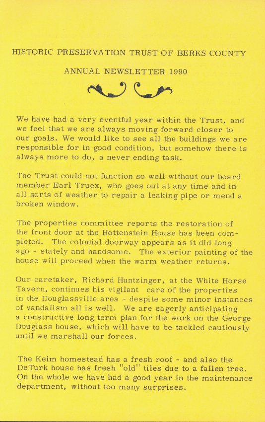
Four page newsletter of the Historic Preservation Trust of Berks County printed in 1990. Piece contains a letter from Mary Pendleton (then Trust president ) updating readers on the restoration progress made at various properties in addition to thanking volunteers, acknowledging donations, etc.
For full text of newsletter see additional images.
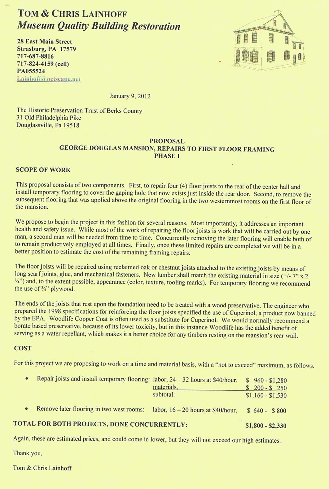
Sites & Structures Committee Report for the January 25, 2012 meeting of the Board of Directors of the Historic Preservation Trust of Berks County
The following is a summary of preservation, restoration, and related work completed and in-progress, with recommended Board action:
Keim House:
Cellar Bulkhead Project:
Framing, cheek sheathing, and rake boards have been installed per proposal. Doors and rest-posts will be installed soon. Paint analysis on other exterior woodwork suggests "Spanish Brown" as the appropriate finish color. Photos 7436 & 7440 show framing, sheathed cheeks with horizontal boards, and rake boards on the frame rafters.
George Douglass House:
Tom & Chris Lainhoff have submitted a proposal [attached] for phase 1 of the stabilization and restoration of the George Douglass house floor framing. Photo 3553 shows the rotted joists at the door in the east eaves wall. The cost for labor and materials would fall between and is not to exceed $1800.-2330.
Board approval is requested. Funding would be provided by Shelley grants and existing balance of contributions toward GDH restoration.
Douglass, Douglass-Jenkins, and "Amity" Store Ledgers
The six bound record books discussed in the November report have been delivered to the HSBC in archival boxes provided by the Trust. The HSBC has issued an Incoming Loan Form [attached] dated 1/3/12 acknowledging receipt of the ledgers and day-books on a loan basis, renewable annually. The Trust has the privilege of removing the books for one-month periods, subject to reasonable access for researchers. The loan document is attached and will be recorded in the archives.
We should consider providing specific insurance for the ledgers and other valuable items, in conjunction with the artifact cataloguing process initiated by Trust intern Allessandro Russo and archivist Jon Hartman. Jon has catalogued the ledgers and day-books for the archives.
Morlatton Parking Lot:
The Construction Agreement with Amity Twp is in final form, ready for signatures when the License Agreement is completed and approved by both parties. We have fixed prices [subject to extras] with the site contractor, subject to Board approval. The complete project budget will be circulated to the Board when finalized.
Leslie Rebman will present the Grant Agreement for approval by the Board and return to the Greenway for signature and 90% draw-down of funds..
The final site plan and E&S Plans were submitted to the conservation District this afternoon. The approval process normally takes 2 weeks.
We have requested our insurance agent Kevin Anderson to quote liability coverage for the parking lots and the additional liability coverage to secure the indemnity requirements of the grant agreement.
Attached are sketches of the details of the log perimeter system.
Tom is working with Chazz Lyons to provide elect. to the site for drill and other power equipment.
Requested Board action:
1. Discuss and approve Lainhoff proposal on GDH floor framing.
2. Decide on cellar door rest-posts [locust from Morlatton] for KH bulkhead entry.
Consider providing a sheltering structure for the KH root cellar to preserve and exhibit it as a study-piece; discuss form and details; authorize preparation of design options.
3. Designate storage space for mission-related items, or other period items deemed worthy of retention as examples of significant architectural elements, to be removed from public and interpreted spaces.
4. Dispose of non mission-related and non-usable architectural artifacts, such as shutters, window sash [after removal of period glass?], doors, etc., in conformity with policy adopted by the Board; Jim Lewars suggested offering disposable items for sale, then for donation if there is no market.
5. Approve parking facility Construction Agreement and Grant Agreement and authorize officers to sign them and License Agreement after circulation to Directors.
The License will provide that the Trust has the rights: to participate in the construction of the parking facility on Township land in accordance with the Construction Agreement and final Plan; to reserve parking spaces [leaving a reasonable number for Trail users and the public] for meetings, tours, and other group activities and events on 100 dates per year for 25 years; to erect signs, gates, and guide-posts to secure the reservation rights; to create the "White Horse Trail" with permeable natural materials; no overnight parking except for pre-arranged encampments or other appropriate events.
Submitted by the Sites & Structures Committee.
Laurence Ward, July 2016
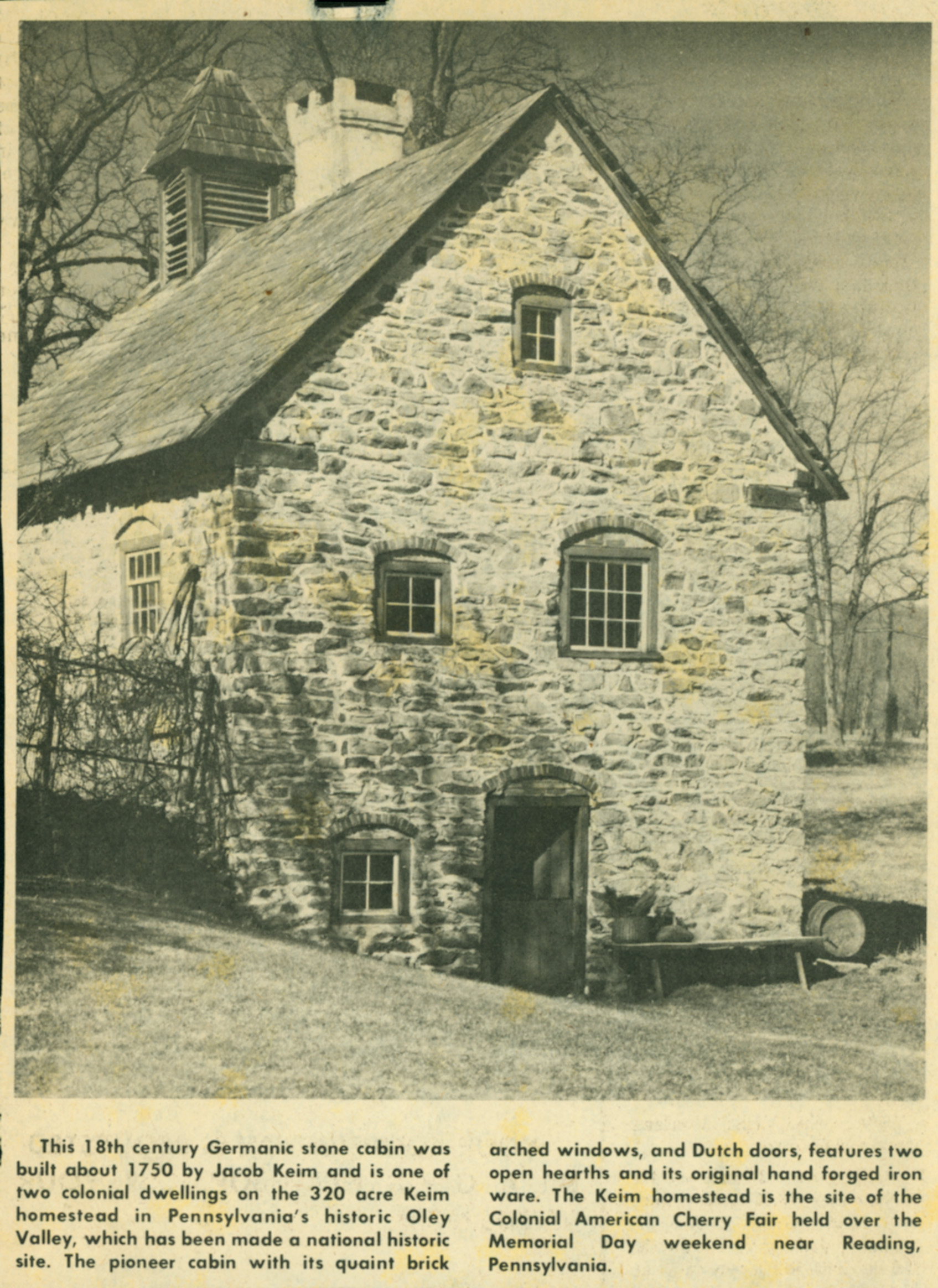
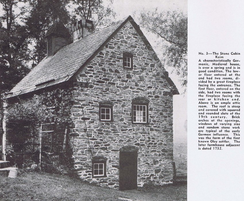
Clipping from an unknown newspaper showing the Keim Ancillary Building (formerly called a "cabin" under the speculation that it had been a Keim "settler's" dwelling preceding the 1753 house) and including a very brief history of the building. Later research determined a construction date of c.1753 and a determination that it was a multi-function farmstead "ancillary" building [Pendleton, Philip, "Oley Valley Heritage, The Colonial Years, 1700-1775," p. 91, caption, and accompanying text, pp. 90-92].
Laurence Ward, updated February, 2021
Keim ancillary workshop structure, halftone image from photo, with descriptive caption, published in the "Dutchman," Winter, 1954, page 18.
Brick arches shown are "relieving" elements when properly constructed to transfer structural loads to the masonry abutments flanking the door and windows. Stonework is laid in random-rubble masonry method.
Details include short timber corner ties joined to wall plates on top of eaves walls. These ties also serve as the eaves-level "quoins" which, with the alternating longer masoned stones stacked at each corner, bind the vertical mortar joints of the corner piers. Similar (though twice as long) embedded timber "plates" appear in both gable walls of the Johan DeTurk house [see DTR09PH100--1001.01.192, and DTR09PH93--1001.01.185].
Later research indicates a construction date of 1753, contemporary with the Keim farmhouse a few yards away and not an early "settler's cabin" as peviously thought (Pendleton, Philip, Oley Valley Heritage, The Colonial Years: 1700-1775, p. 91, caption and accompanying text, pp. 90-92).
Laurence Ward, updated February, 2021
NHL SCRIPT - KEIM HOMESTEAD
Presenting a rich array of architectural elements and details from the German-American vernacular architecture of the mid-eighteenth century, the Keim Homestead stands in the first rank of domestic properties that portray this important tradition within America's vernacular architecture.
The Keim Homestead is nationally significant under Criterion 4 as an exceptionally illustrative and intact example of early German-American domestic vernacular architecture. The two nationally significant buildings on the homestead, the Main House and the Ancillary Building, both constructed circa 1753, represent methods of construction, elements of architectural decoration, and patterns in the layout and design of dwellings and domestic outbuildings that were characteristic of the German-American tradition in its period of fullest expression circa 1740 to circa 1775.
In plan, the two buildings embody the lifeways expressive of the culture of the eighteenth-century German-speaking immigrants from the upper Rhine Valley and adjacent European regions as this pattern for social and economic life evolved amidst the conditions encountered by the settlers in the New World environment.
The Main House exemplifies the Flurküchenhaus or entry-kitchen house type, the predominant multi-room plan constructed by German-Americans in this period, particularly prevalent in the early German-American "heartland" extending in a crescent-shaped region between the Delaware and Shenandoah valleys. It appears that this specific house type represented an American development evolving over the years about 1690 to 1720, one in which German-speaking immigrants in Pennsylvania adapted elements, such as the five-plate jamb stove and the centrally positioned chimney, which were derived from the European vernacular tradition.
The German-American ancillary building was an auxiliary structure that effectively served as an extension of the main dwelling under a separate roof.Ancillary buildings could be built later to augment the domestic arrangement, or could represent an older cabin adapted for the purpose, or as in this case they could be built en suite with the main dwelling. Another example of a form that evolved in America incorporating elements derived from the European tradition, the ancillary was typically constructed on an embanked site and housed discrete spaces devoted to residential purposes, craft work, and food processing or storage. In the Keim Ancillary, an unusually early surviving example, the first-floor level served primarily as a workshop. The significance of the Keim Homestead is heightened by the presence of the remarkably well preserved turner's workshop room, quite possibly the earliest extant essentially intact woodworking craft workshop in the nation.
Overall these two buildings maintain a high standard of integrity in design and intactness of historic fabric relative to their age of more than 260 years. Modern plumbing and heating were never installed. With the noteworthy exception of Schifferstadt (also present for current NHL review), virtually all individually owned examples of German-American domestic properties had their jamb stoves removed, and that was done at Keim. In the ancillary, the partition walls and
the workshop workbench were removed, though clear evidence of their former locations remains, so that the way in which the building originally functioned is clearly discernible.
"Philip Pendleton, May, 2016"
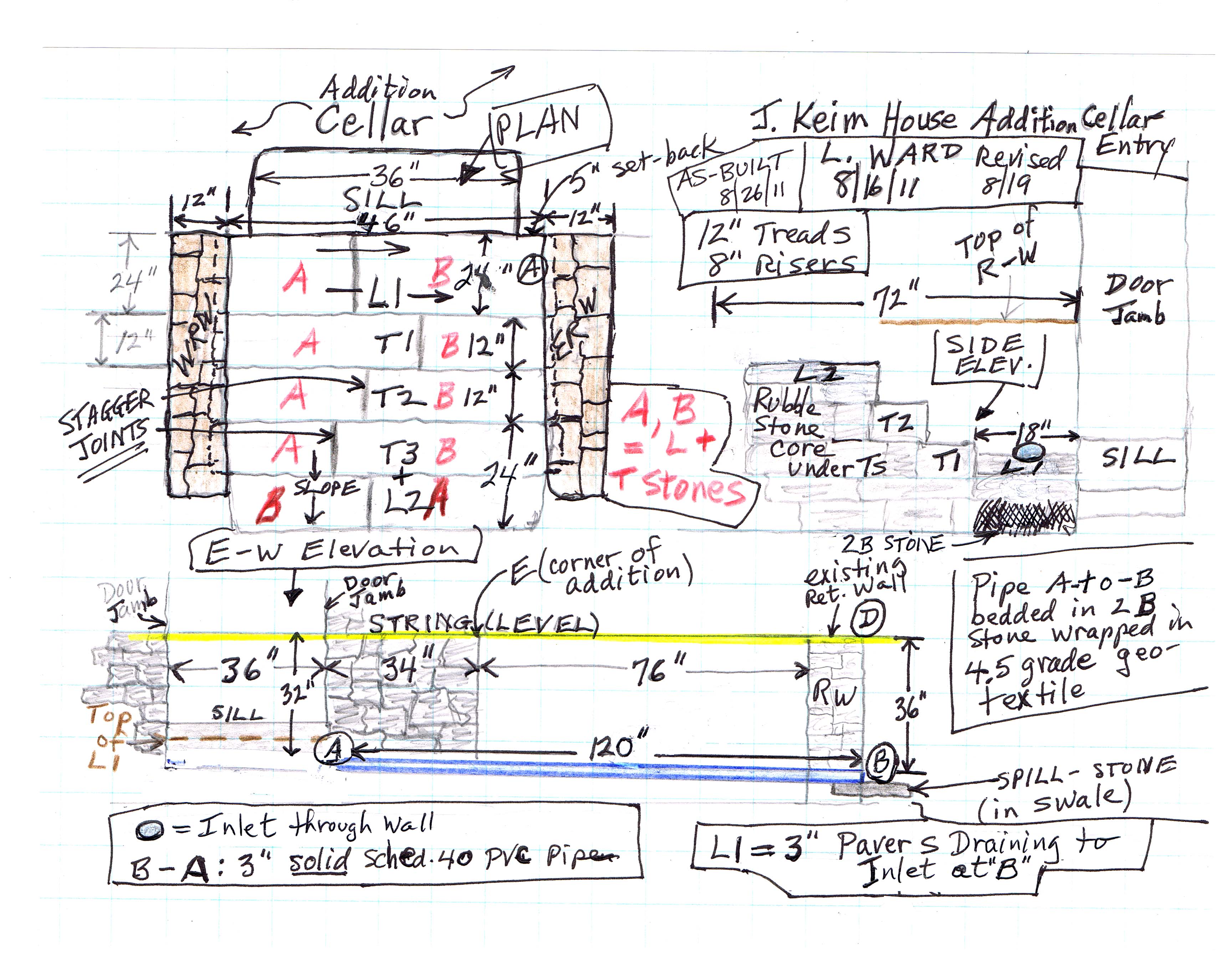
Digital images of 2 field notes drawings and a series of 8 digital photographs showing the cellar entryway constructed in summer, 2011 at the c.1800-1820 addition to the Jacob Keim House. During most of the past 90 years, the addition-cellar doorway [Image #3, photo 3676, 5/23/11] and its approach, an earthen ramp, were sheltered against direct precipitation and roof runoff by the porch built in about 1930 [see Record KR11PH3]. Removal of the porch in July, 2011 eliminated the shelter it afforded, and exposed the cellar doorway and the ramped grade-path to direct precipitation and roof runoff, as well as ground-surface "sheet" flow to the doorway, a virtual "funnel" located at the low-grade along the southern foundation walls [Image #4, photo 5310, 8/13/11]. Significant rainfall and the resulting surface-flow inundated the addition cellar between the time of removal of the porch and the installation of the retained cellar steps and pipe draining the paved lower landing of the new stair-block.
The stone stairway and retaining walls shown in the two sets of drawings and photographs in this record were designed to mitigate the ground and roof runoff into the addition cellar through this doorway. The integrated stair-wall structure consists of:
(a) a lower landing floored with flat stones ["flags"] laid in a random ["crazy"] paving pattern [Image #5, photo 5642, 8/25/11, and Image #6, #5804, 9/1/11]
(b) two intermediate steps formed by two stones ["treads"] each, with their inward faces constituting "risers" and
(c) two larger stones forming an upper landing and creating a natural riser, with treads level with the existing grade situated 24 inches above the lower landing pavement.
The tread-stones and two-stone upper landing are supported on a "rubble" stone core set in mortar, and bedded several inches into the adjacent retaining walls, producing reciprocal mechanical bond and a strongly integrated stair-block.
The walls flanking the steps will serve the usual function of retaining the soils abutting the stairwell, and will provide the additional benefit of diverting the ground runoff around the entry-way to swales conducting the flow down-grade [to the south] from the yard area south of the house and federal-era addition [Image #7, photo #5841, 9/3/11].
Roof runoff and direct precipitation into the "catch-basin" formed by the lower landing will be conducted to an absorption and discharge area by a solid 3-inch Schedule 40 PVC pipe extending at a ¼-inch per foot pitch through the backfill and two retaining walls to the lower grade 9 feet east of the cellar doorway.
The backfill around the new cellarway structure includes a bed of small stones serving as a "French" drain wrapped in a 4.5 gauge geo-textile filter fabric deployed to minimize clogging from soils above the stone drainage course. The water collected in this system will pass through the earlier retaining wall within the opening serving as the conduit for the drain pipe from the lower landing.
Tamped clay was back-filled against the building and retaining walls after insertion of a vertical sheet material forming a water barrier ["Delta-Drain"; see photo Image #8, #5650, 8/26/11] to protect foundation mortar from disintegration. Mixed soils were then filled-in on top of the clay. The area will be sodded or seeded to inhibit erosion.
The as-built stair-wall structure is shown in photos Image #9, 5834 and Image #10, #5836, 9/3/11.
DETAILED CAPTIONS
Image #3, 3676: Doorway to addition cellar prior to removal of porch and construction of retaining walls and stone steps.
#4, 5310: Excavation for cellar steps and cheek walls.
#5, 5642: Retaining walls, steps and landings substantially completed, prior to leveling ["flushing"] up east retaining wall.
#6, 5804: Both retaining walls leveled; Delta Drain membrane set in vertically against sub-grade stonework to conduct soil moisture to stone drainage course.
#7, 5841: Rough grades and drainage swales established.
#8, 5650: 3-inch stones back-filled as drainage path.
#9, 5834 and #10, 5836: Completed walls, steps and raked grades.
Laurence Ward, 2011; updated January, 2021