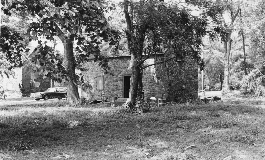
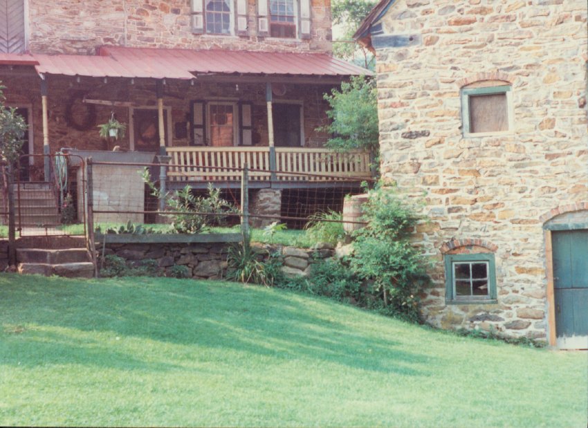
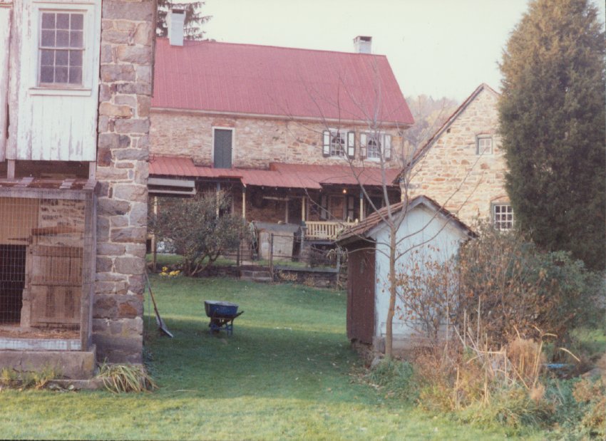
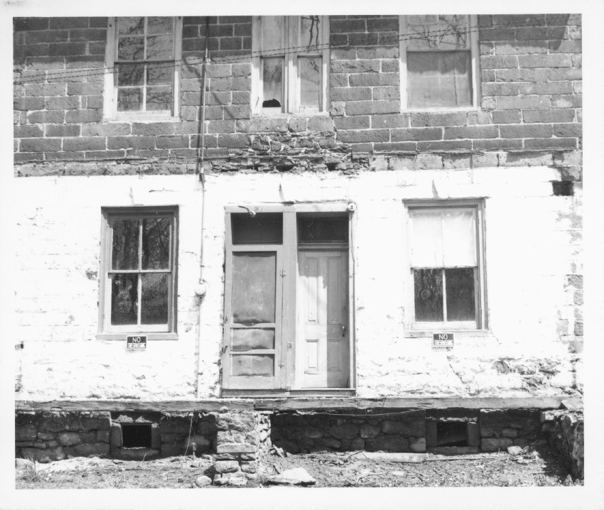
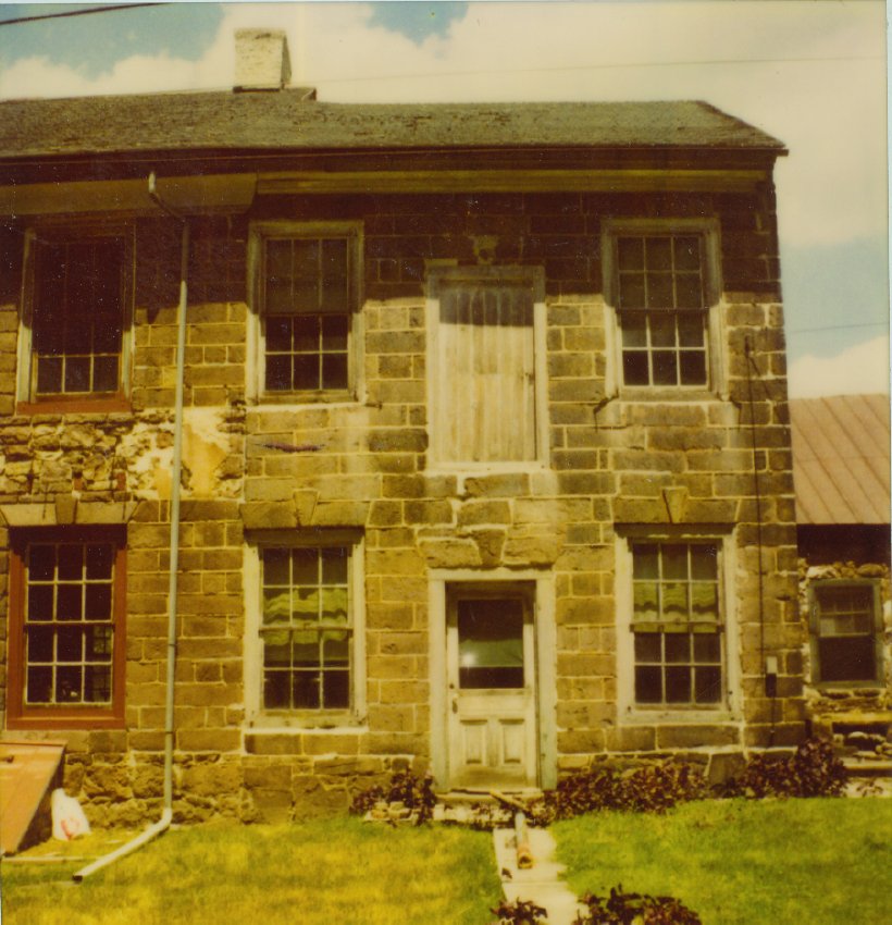
Black & white photographic print showing aftermath of flooding from hurricane Agnes in 1972. Image depicts southwest perspective view of Mouns Jones House (left) & Bridge Keeper’s House (right). The “Bridge Keeper’s House”, now re-named the “Michael Fulp House” in recognition of its first owner/occupant, in the center of the photo is identified by the cellar entry under the window and the door location in the right [southern] bay. Segments of the masonry walls, chimneys, roofs [both are complete replacements] and window framing of both buildings have been restored, replaced, or reconstructed in preservation campaigns during the past half-century [to 2015].
Note written in blue pen on verso reads, "STARTING THE CLEANUP"
See MVPH4 thru MVPH24--1003.01.009 thru 1003.01.029 for additional images of hurricane Agnes flooding.
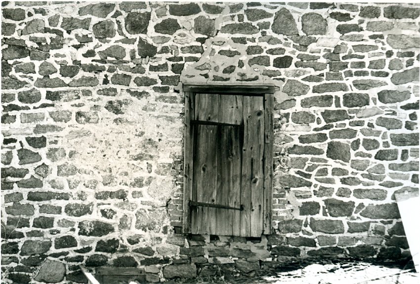
Digital image of original photograph taken by Steve Kindig. Image shows exterior view of door and hardware in the west masonry wall at upper (first floor) ground level. The oak lintle and tops of jambs of the cellar kitchen window are seen along the lower left edge. Brick infill between door jambs and masonry indicates later period of doorway (19th century).
See discussion to DTHPH1--1001.01.021 regarding the 19th-century addition accessed through this door.
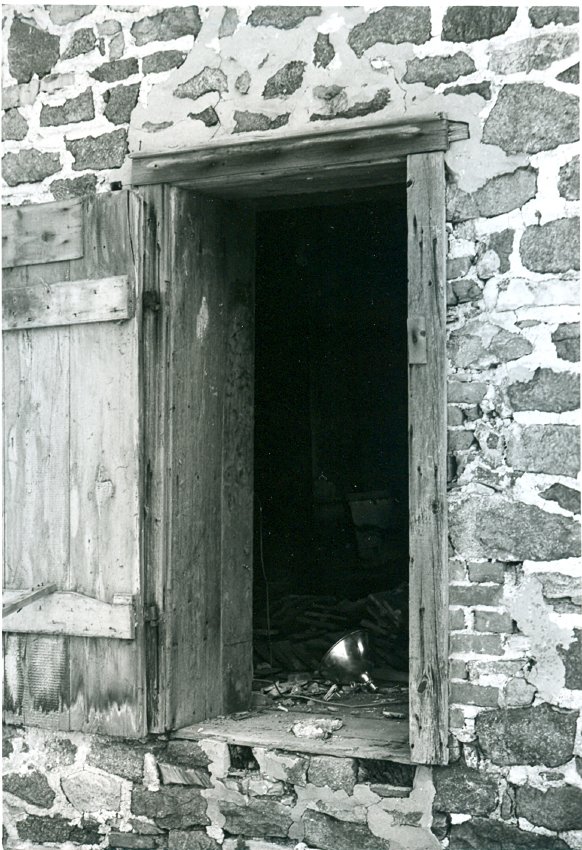
Digital image of original photograph taken by Steve Kindig. Image shows former doorway through west masonry wall providing access between first floor and 19th-century kitchen addition (removed). Brick infill between door jambs and stone masonry indicates later period of doorway (19th century)
See DTHPH1--1001.01.021 for discussion of the removed addition.
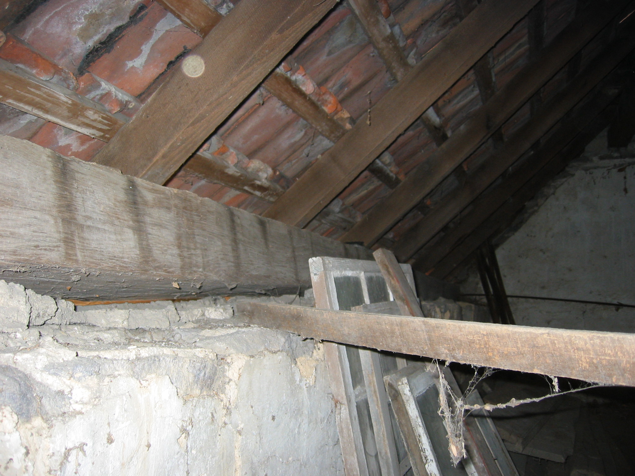
Southeast portion of DeTurk House attic granary showing east eaves wall plate [large hewn beam extending into the corner starting at the left edge of the photo]. This plate is rotated several degrees from the horizontal and curves outward, either from roof thrust or possibly because of a prior structural function, probably in another building{1}. Although insufficient "curing" [drying through evaporation] is possible as a contributory cause of the curvature, it is quite unlikely that the original builders would have installed a "green" timber for the important function of a wall plate deployed to carry the substantial loads of a roof and its timber support structure.
The roof rafters and lath were installed in the 1970s. The early clay tiles were assembled from several sources, including a group found in this 1767 building (see DTHTX18--1001.01.017 manuscript sheet headed ‘[DeTurk] Restoration Plans’ paragraph 2, which states "Enough tiles are available for the roof: 1000? Stored in DeTurk House, 1st floor, 700? Stored at Jack Keller’s farm…600? stored at Dr. German’s house (donated by Paul Blatt, Bernville)."
The iron tie rod on the right (shown more fully in the left half of photo DTR09PH102--1001.01.198) was installed in the 20th century to restrain roof thrust. This retrofit was necessitated by the inadequate integration ["tying"] of the wall plates into the structure in the original building campaign. This problem was compounded by the inability to install continuous tie beams from eaves-corner to eaves-corner because of the chimney in the north gable wall and the granary door in the south gable wall. A secondary possible cause of the partial failure of the roof support system was the replacement of lighter roof covering, wooden shingles, with heavier slate and clay tiles during various re-roofing projects on the building. This would impose substantially greater lateral thrust on the rafter plates and the masonry stone courses supporting them, tension on the rafters and their support members.
FOOTNOTE
{1} The darker vertical bands, possibly from joists bearing on this timber and reducing oxidation from exposure to air, on the inner [west] face of the rafter plate{n} might indicate prior use as a summer beam. The outward curve [which would project downward if the plate were rotated to set the bands facing upward under joists], would probably be caused by deflection of the beam from many years of load-bearing in functioning as a “summer” or girder.
{n}so called because of its primary function as the “wall” plate [generically, any timber borne on, or embedded in, a masonry wall] supporting the roof rafters and the loads they bear.
Laurence Ward, 2009, updated March 2021
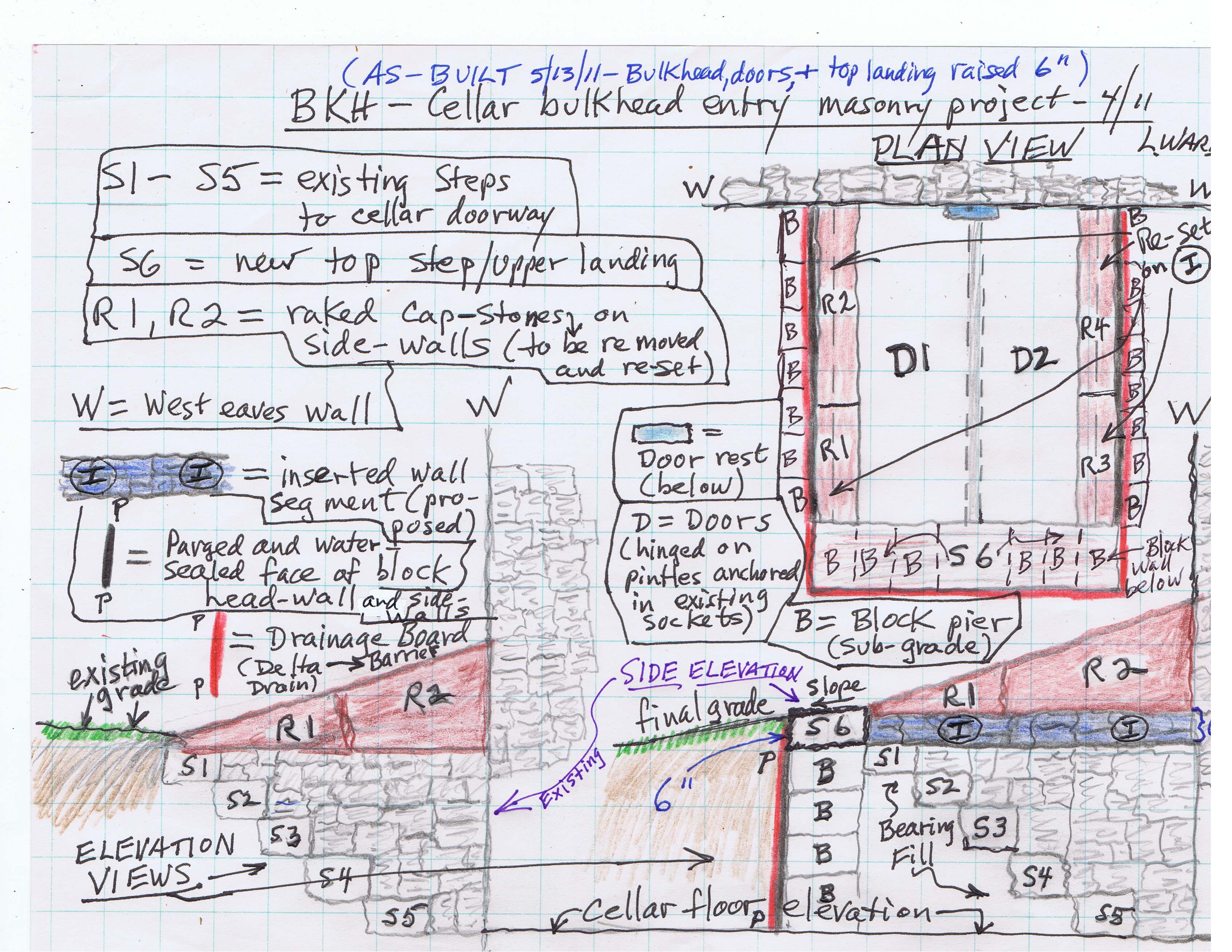
As built drawing of April, 2011 masonry project to stabilize and waterproof the cellar "bulkhead"{1} entry at the Michael Fulp (Bridge Keeper's) House.
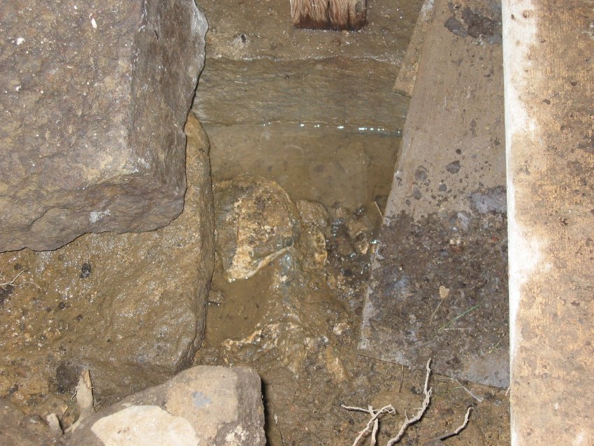
For several years prior to this reconstruction project, rainfall of ½-inch or more within a 24 hour period would produce several inches of water (occasionally 6-8 inches or more) on the cellar floor of the Fulp house. It was evident that the bulk of the incursion was from 2 sources 1) ground runoff ["sheet-flow"] cascading down the cellar stairs and 2) percolation through saturated soils and permeable fill layers built up as the river bank and alluvial plane were raised to mitigate periodic flooding.
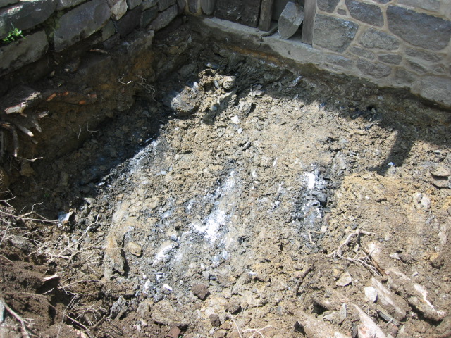
Most of this accumulation was the result of the lack of a moisture barrier outside the flank walls ["cheeks"] and a permeable support bed [a loose mixture of clay, gravel, and loam riddled with coal particles deposited during river flooding] under the top stone step. Although the pre-historic clay bed is excellent bearing material, the grade-raising alterations compromised the stability of the clay. There were no discernible "footing" stones to distribute and stabilize the masonry loads imposed by the cellar entry structure.
This "bulkhead", situated in a shallow grade-basin, was a virtual "funnel" for pooled ground water, augmented by runoff from the roof above the bulkhead.
The remediation plan consisted of three elements:
A. Raising the entire bulkhead entry structure 6 inches above pre-existing levels, and adding a granite stone slab landing ["S6" in drawing, 65 inches long, 18 inches wide], which varies in thickness from 6 inches at the riser to 11 inches at its outer face above the previous level of the top step ["S1"] of the descending staircase. This massive stone was "man-handled" into position with rollers and digging bars. It will dam much of the ground-surface runoff which previously flowed down the cellar steps.
B. Laying up a continuous perimeter wall of concrete block to support and buttress the flank walls, the raking cap stones ["coping"], the shoulder-walls abutting the flanks, and the added upper landing stone. The outer face of the sub-grade block wall was pargeted with mortar, which was brush-coated with a conventional waterproofing fluid; the interface between the coatings and abutting soils was lined with overlapping sheets of "dimpled" drainage board [Delta-Drain] with an adhering filter-fabric [the same "geotextile"-lined moisture barrier which was installed on the exterior face of the foundation walling of the entire building]. The lower portion of this impervious sheet material was folded 90 degrees and extended outward across the excavation floor in order to direct the down-flow through the dimpled exterior plane of the sheet and away from the base of the block wall and its "lean concrete"{2} footing pad. Water collected by this gravitational conduction system will flow into the perimeter drains around the foundation walls and footings [see MFR10FN2--1005.01.058] to a remote discharge. C. Fabricating and installing board-and-batten ["ledged"] doors "double-hung" on "pintles"{3} driven into the mortised raking cap stones on the cheeks. The coping now sits 6" higher than its pre-restoration elevations, presenting an improved water barrier along the flanks of the entry structure. After this process was completed, much less water accumulated on the cellar floor after substantial rainfall in the region.
Future river-flood incursions will be mitigated with a pumping schedule.
FOOTNOTES
{1} a term which apparently emerged in the building trades in the mid-19th century, probably in New England. The word "bulkhead", sometimes called a "cellar cap" in 18th century documents [Lounsbury], does not appear either in the 1786 Philadelphia Carpenter's Company "Rules" or in the 1797 Chester County "Practical Carpenter's Guide" in their respective treatments of "cellar doors." The Philadelphia "Rules" describes and prices only wooden "cheeks" and "sills" from "scantling" [dimensioned lumber]. The 1797 Chester County "Guide" provides for the less expensive option of stone for these elements, as well as "sawed scantling." Roughly vertical mortar joints between the stone cheeks and the foundation walls indicate a later date for this addition.
{2} relatively dry ["stiff"] mortar hardened with clean "2B" stone. {3} The term "pintle" is significantly later than the 18th century descriptor "hook", which was often used in conjunctive forms such as "hook-and-eye", "hook-and-hinge", and "hook-and-strap [hinge]".
Larry Ward
Series of 3 color photographic prints of detail views of the additions on the southeast gable end of the 1765 George Douglass House:
Image #1, Douglass House, perspective view of the 2 story Amity Store addition with freight door to 2d floor ware-house, and 1 story addition used for processing meat and other food products as part of the "general store" mercantile functions of the 4-structure complex. Store ledgers commencing in the late 1760s and owned by the Trust are kept by in archival conditions by the Berks History Center, where they may be viewed on its premises.
Image #2:The white-painted wall [removed in the early 21st century] connecting back corners of the 1765 house and the 1-story food processing structure is not original to the period. It enclosed a brick-paved yard facilitating the passage of people, food ingredients, and finished goods for sale in the store facilities in the period between the house [which included the original Amity Store in the room fronting the original kitchen from the late 1760s until the construction of the store addition c. 1798-1810], the 1-story addition, the store addition, and the stacked root cellar and smoke-house between the store addition and the 1-story structure. A late 18th century document in the Trust's collection is an inventory of "Pork in the Smoke House", reciting sales from and processed additions to the pork to be smoked for sale.
Image #3: Elevation view of the Store and 1-story additions. The chimney at the gable-end of the 1-story addition vented a very large fireplace used in connection with the processing of food for sale and for the Douglass family, and for their guests and business visitors, and probably for those employed in the various enterprises conducted by George Douglass Sr. and Jr. from 1765 to the death of George, Jr., c. 1832.
Larry Ward, August, 2023
Digital photographic print showing door and window along eastern elevation. Image depicts conditions existing immediately
prior to and necessitating the 2009 restoration of building.
This is a low resolution image (72 ppi).
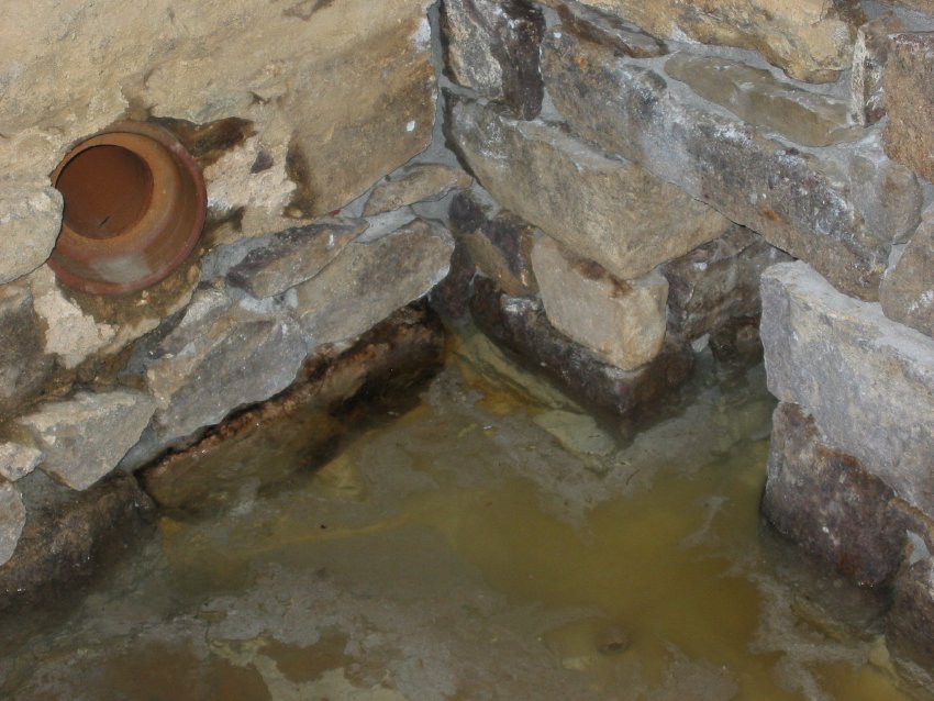
Restored floor drain inlet through east foundation wall of kitchen. See DTR09PH14--1001.01.095 for a pre-restoration view of this corner.
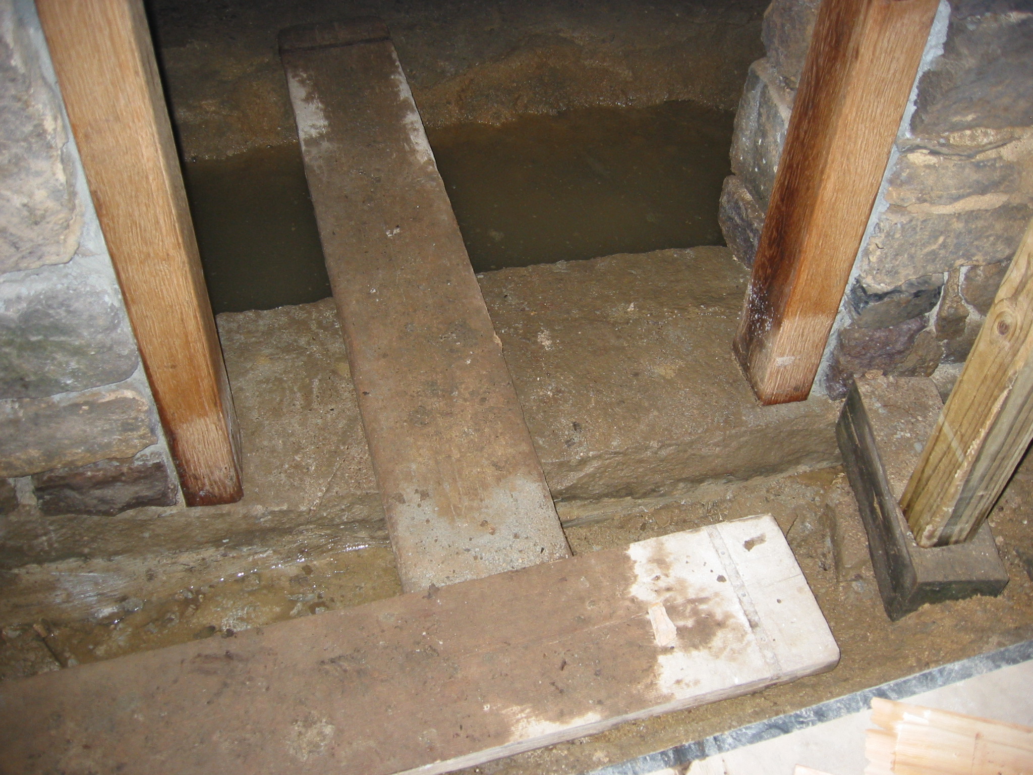
The bottom of the 6-inch PVC pipe inserted in the upper half of the rectangular drain tunnel is 8 inches below the door sill [2 inches lower than the restored floor level will be]. The pipe will drain the kitchen floor when the creek level is lower than the water level in the kitchen, provided the water level in the kitchen is no more than 8 inches below the sill.
It is expected that this drain, in conjunction with the dual channel-drain system to be installed in the stairwell outside the kitchen doorway, will lower the water table inside and outside the door sill by 6-12 inches within hours after heavy rain ceases and the creek recedes. Under conditions preceding these installations, the water table receded as little as 1 inch [or less] per day {1}, depending on the degree of saturation of the surrounding watershed.
Back-flow will be controlled by a check valve at the outlet of the pipe. Setting the drain inlet any lower than this would create reverse ["negative"] pitch to the outlet elevation at the bottom of the pipe.
The terra-cotta pipe through the north wall was installed in the 1970s to drain the modern kitchen floor, which was 18-24 inches above the original [ to be restored] brick-paved floor elevation, too high to reduce saturation of the lower foundation wall and its mortar joints.
Provision will be made to install an emergency sump-pump in the northeast corner segment of the sedimentation trough to drain the cellar in extreme flooding conditions. A sleeve will pass through the existing terra-cotta pipe in the north wall [upper left quadrant of photo] for the outlet hose from the pump.
This photo also shows the restored foundation walls converging at the northeast corner of the kitchen, now plumb, re-mortared, and stabilized. This restored stonework was repointed in April, 2010 using hydraulic mortar below the high water-table level.
The Left jamb of the early drain is 10 inches from the northeast interior corner. The right edge of the terra-cotta pipe is 14 inches west of the same corner.
The darker stones at water level are the base blocks of the foundation and are set on a leveling layer of sandy clay on limestone bedrock, which provides a stable natural "footing" for the masonry wall system {2}.
FOOTNOTES
{1} Numerous photos and water table level readings taken between July, 2009 and April, 2010 clearly demonstrate the slow rate of percolation of ground water accumulations away from the building and into the creek.
{2} Less than two miles south of this building the working face of a limestone quarry is over 400 feet high.
Laurence Ward, 2010
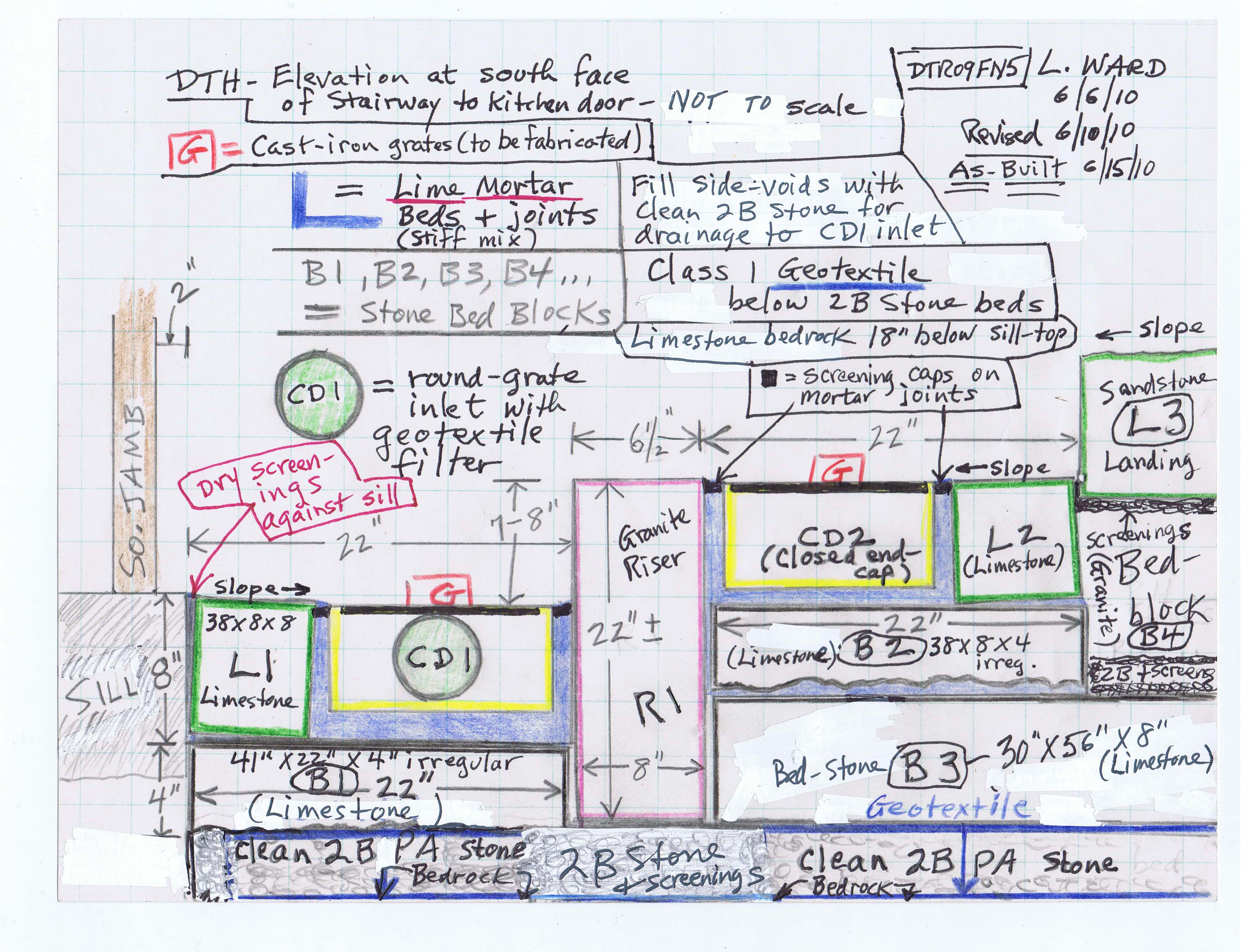
South elevation detail sketch drawing of June, 2010 installation of stone staircase and channel drains at DeTurk House kitchen-cellar entry.
See DTR09PH134--1001.01.230 for photographs of this installation.
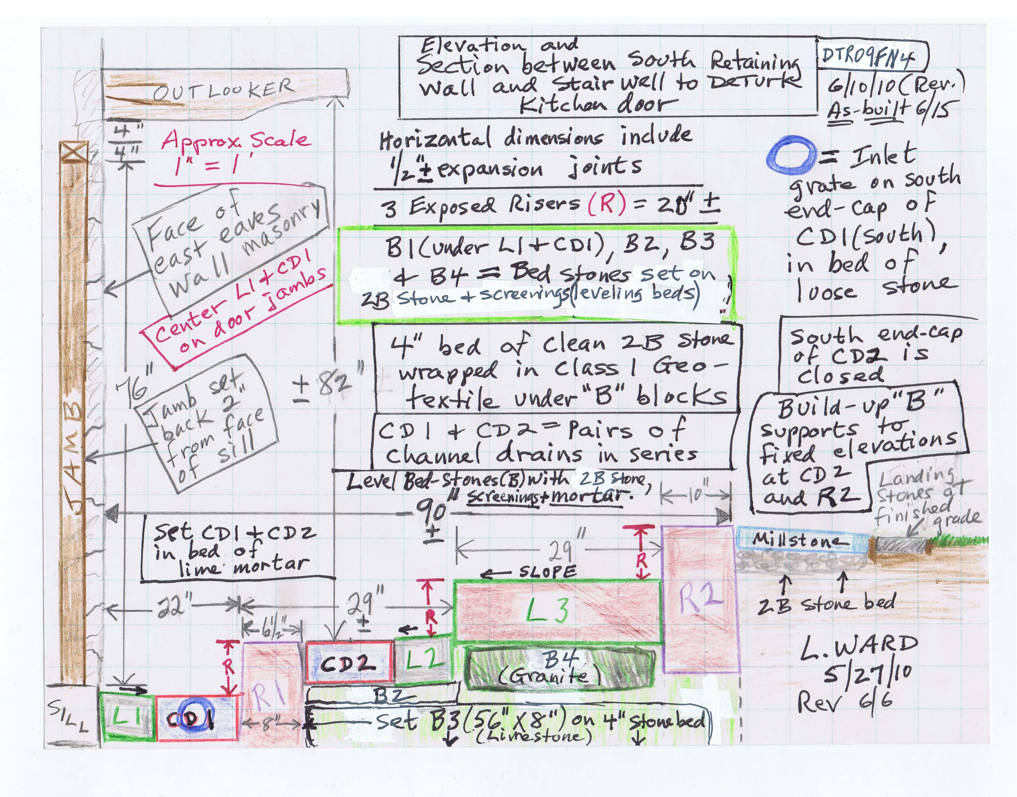
South elevation sketch drawing of June, 2010 installation of stone staircase and channel drains at DeTurk House kitchen-cellar entry.
See DTR09PH134--1001.01.230 for photographs of this installation.
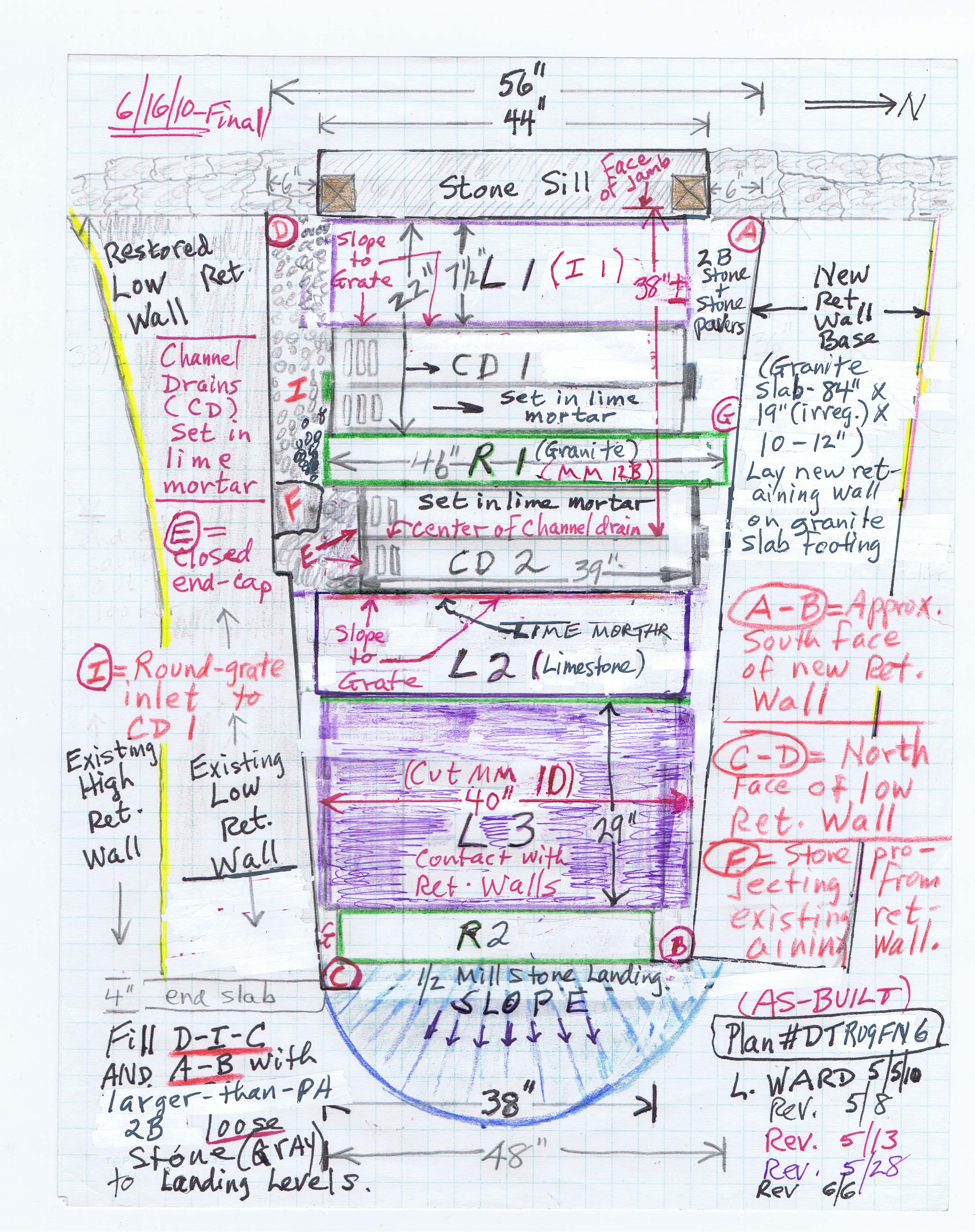
Sketch plan drawing of June, 2010 installation of stone staircase, north retaining wall, and channel drains at DeTurk House kitchen-cellar entry.
See DTR09PH134--1001.01.230 for photographs of this installation.
Series of 32 digital photographs showing the construction of the exterior stone steps to the lower-grade level kitchen doorway at the DeTurk House. Full captions for numbered photos appear below.
June 14, 2010
2634: Brittle top layer of limestone bedrock found 18" below top of door sill.
2635: Chipped and fractured bedrock stratum under door sill.
2636: White-veined blue limestone bedrock at bottom of excavation for staircase. This is the same [Dolomitic] limestone under most of the Oley Valley; in a quarry about 2 miles to the south, where the “table” of stone is about 400 feet thick to the base of the quarry face.
2637: White-veined blue limestone bedrock at bottom of excavation for staircase.
2638: Sizing and cutting geo-textile filter fabric for stone-bed underlayment.
2639: Geo-textile fabric covering bedrock.
2640: Loading "2B" clean stone onto geo-textile fabric.
2641: Leveling 2B stone bed.
June 15, 2010
0001: Rubber-tracked Kubota 161 Mini-Excavator mobilized to excavate, set bed-stones, step-blocks, landings, and risers forming the staircase.
0002: Lower limestone landing ["L1"-see Field Notes sketch-drawings DTR09FN4--1001.01.231 & DTR09FN5--1001.01.232], which is 41inches x 22 inches x 4 inches, set on irregular ("rock-face") limestone bed stone ["B1"] to support L1 [lower landing, against sill] and CD1 [lower channel drain, at same elevation as L1].
0009: 30 inches x 56 inches x 8 inches limestone bed-stone ["B3"], positioned as shown in DTR09FN5--1001.01.232 to provide continuous solid support from bedrock upward through bed-stones, which bear step-blocks ["landings"], risers, and channel drains.
0016: L1, R1 [granite riser] & B3 set in final alignment on 2B stone and screenings leveling bed, and CD1, set in a lime mortar bed with mortared [vertical] side-joints capped with screenings.
0017: 360 degree leveling laser used to set elevations of landings and channel drain grates, using top of sill at north door jamb as reference datum.
0019: 38" x 22" x 4" with one of its larger surfaces on (irregular "rock-face") limestone bed stone ["B2"] to support upper limestone step-block ["L2"] and CD2 [upper channel drain].
0020: setting B2.
0023: setting and leveling B2 on stone screening bed.
0026: setting and leveling L2 on stone screening bed.
0030: Grappling granite bed-stone [ "B4", 38" x 22" x 8"] into position, with 2-plate "thumb" attachment, to support sandstone landing ["L3"], which is 40" x 29" x 8".
0031: Transporting B4 down embankment to staircase excavation.
0032: Preparing to set B4 in place.
0033: screenings bed leveled to receive bed-stone B4.
0037: B4 in place and leveled on screenings bed.
0052: L3 grappled with excavator bucket and "thumb" to its site.
0054: leveling L3.
0058: Setting mortar bed for CD2.
0063: Troweling mortar into joints flanking CD2.
0064: Screening caps on channel drain mortar joints.
September 7, 2009
1084: East eaves wall detail and kitchen doorway prior to completion of staircase, retaining wall, and drains protecting doorway and foundation walls.
July 3, 2010
104: East eaves wall detail and kitchen doorway after completion of staircase, retaining wall, and drains protecting doorway and foundation walls
Laurence Ward, 2009, UPDATED Oct 2021 and September, 2022
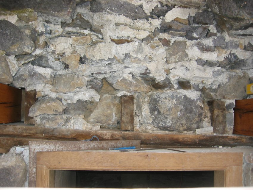
View of wall above kitchen door after removal of exterior layer [“wythe”] of stones, which were distended and out of plumb.
Stones removed from above the doorway were laid out on the ground in "mirror" position and were re-laid and "mudded in" [set and bonded in bed and joint mortar] in their original positions. Repointing of this wall segment was completed in April, 2010, using a traditional lime-mortar mix consisting of lime, water, and sand “aggregate” from the nearby Little Manatawny Creek.
Details shown include the replacement door-frame lintel; the "stacked" pair of bearing plates; end grain of three original floor joists; original bonding [also "bed" or "setting"] mortar and the "keyed" inter-positioning of stones of various sizes, shapes, and setting angles characteristic of random rubble masonry; filleted corner ["quarter round"] bead along jamb and lintel edges ["arrises"]; and a portion of the replaced outlookers emerging from wall [reddish-brown wood surfaces at right and left edges of photo]. Also apparent is the 2-inch deflection of the paired "wall plates," the upper member bearing the joists, now deflected from south to north [left to right] across the photo partially behind the carpenter's square, which is level.
See DTR09PH92--1001.01.184, a series of 18 photos showing the removal of these stones above the doorway as well as a reconstructed view prior to repointing.
Laurence Ward, 2009, updated March, 2021
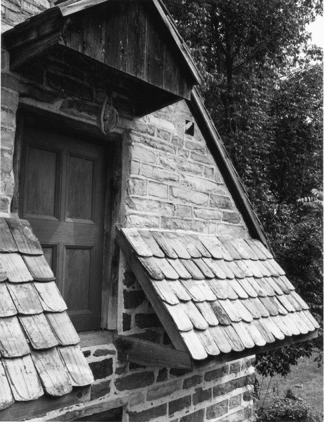
Black & white photographic print of DeTurk House showing a detail view of second-floor doorway, gabled pent hood, and pent roofs. Note on reverse of photo says "copyright [symbol] Steve Myers Studios 1990."
Details include: gabled pent hood, hyphenated pent roof, replicated two-board attic door with moldings applied to simulate a paneled door.
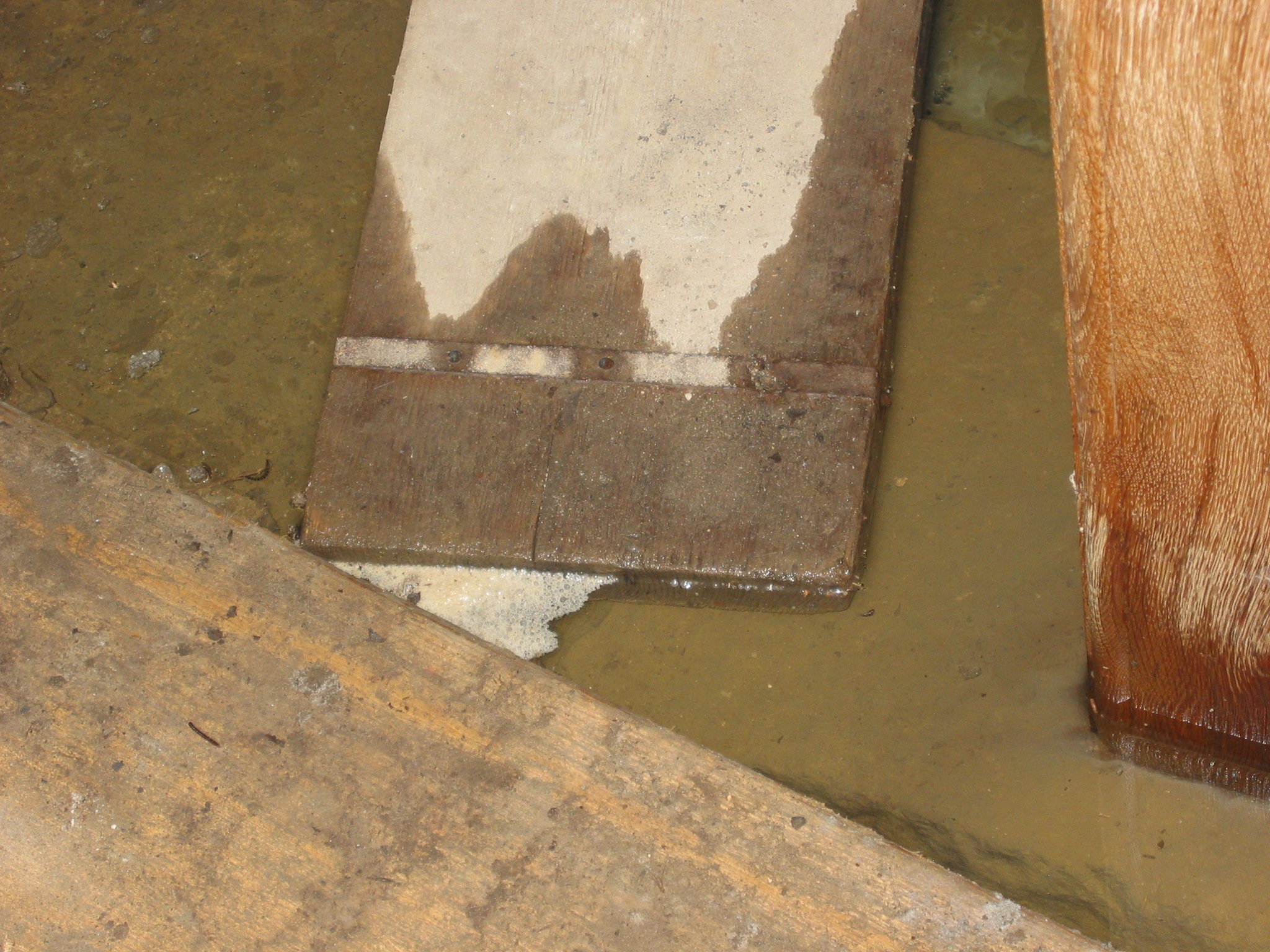
Exterior view of north door jamb foot in one inch of water above stone sill after 2 inches of rain in 36 hours.
This water level would submerge the restored brick-paved kitchen floor under seven inches of water and place the foundation wall and its exposed mortar joints in contact with more than one foot of standing water, which recedes from that level very slowly by natural percolation through the soils, wall pores, and limestone bedrock. The restored original drain tunnel, with an enclosed and backflow-protected gravity drainage course, will discharge these water levels in a fraction of the elapsed time required in the absence of these facilities, and will significantly reduce both the duration and extent of these incursions. This system will substantially extend the life expectancy of the pointing and bonding mortars, materially prolonging the durability of the masonry foundation.
Laurence Ward, 2009
Detail view of jamb [top-center], door sill [upper center], and retaining wall blocks (left third of photo), [detail at lower left corner of DTR09PH51--1001.01.135].
Blocks along left third of photo are foundation stones of the low retaining wall and masonry abutment south of the kitchen doorway before restoration [see DTR09PH61--1001.01.145 for restored view of this abutment, and DTR09PH125--1001.01.221 for a view of the relaid low retaining wall abutting the higher retaining wall to its south.]
Laurence Ward, 2009
Exterior view of restored [original] kitchen door sill and lower portions of replacement oak jambs. The [original] stone sill was shifted 2-3 inches to the right [north] to accommodate the adjusted jamb alignments [see DTR09PH4--1001.01.124 for discussion of the effects of this relocation of the sill on the relationship between the doorway jambs, lintel, sill, abutments and hood outlookers, and DTR09FN3--1001.01.176 for a field notes drawing of the probable historic and modern locations of those elements].
See discussion to DTR09PH60--1001.01.144 regarding the water table inside and outside the stone sill and necessary mitigation plans (see DTR09PH66--1001.01.150) designed to protect the structure from its effects.
Masonry abutment piers were re-pointed with locally formulated mortar in 2010, applying a hydraulic-grade mix to joints below finished grade or below the high water table range.
Laurence Ward, 2010
Color photographic print showing details of the south elevation view of the Keim House and southwest gable wall of ancillary structure.
Details include: brick relieving arch, chevron door, portion of 1930s porch.
Color photographic print showing detail of the south elevation view of the Keim House. Note that portions of the Keim Cabin, Keim Barn, and Keim Outhouse (right) can be seen in this photo.
Details include: chevron door, brick relieving arch, 1930s porch.
Original black and white photographic print showing detail of southwest elevation view of the White Horse Tavern after removal of Victorian porch and before restoration. Note (in blue pen) on reverse of photo reads, ”WHITE HORSE TAVERN. NOTICE PARTITION IN 2ND FLOOR WINDOW AND 2 DOORS IN FRONT TO ACCOMADATE [sic] 2 APTS.”
Details include: Coursed-and-dressed masonry, random rubble masonry over later double entry indicating position of early tavern doorway hood.
See additional images for digital copy of reverse of photo.
Image #3 [#4416, 041215] is an earlier mid-20th elevation detail view of the apartment entries, later window sash, and porch on the SW eaves wall.
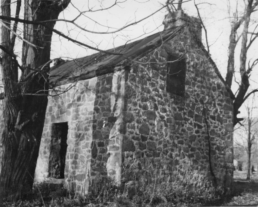
Black and white photographic print showing southwest perspective of west eaves wall, south gable wall, and severely damaged roof.
Details include: random rubble masonry [south gable wall and west eaves wall]; door and window frames; stove chimney on north [left] gable [collapsed in March, 1967 or removed during 1970 restoration]; off-axis attic window; off-axis south [right] gable-end fireplace chimney.
Note written in blue pen on verso reads, "Bridge House 1968" [sic, the building had partially collapsed in 1967 and was not re-built until late 1970 into 1971].
Note stamped in black ink on verso reads,
"Theresa R. Beard
XXXX [address withheld]
Douglassville, PA. 19518"
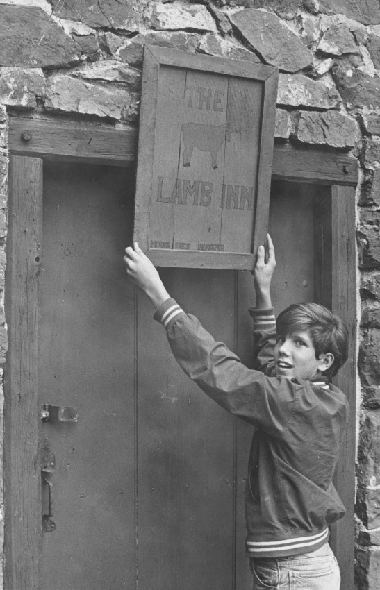
Black and white photographic print printed showing detail of Eastern doorway of the Mouns Jones House. According to the note on verso this photo was taken during preparations for [Mouns Jones] Country Fair, held annually for many years.
Details include: Rubble stone masonry; pegged-tenon joints between jambs and lintel of door-frame.
Note written in blue pen on verso reads, "Getting ready for 1970 Country Fair"
Note stamped in blue ink on verso reads, "OCT 2 1970 Photographer: J. Sheridan Evans"
Series of 5 color photographic prints of detail views of the George Douglass House and additions.
Image #1 shows an elevation view of the c. 1798-1810 Amity Store addition to the 1765 "Manor House". The door above the entrance door is a "freight" door to the 2d floor wares storage apace for goods sold in the store below.
Images #2 & 3 are an elevation view of the façade of the 1765 house. Two of the 3 Federal-era attic dormers survive and were removed in a late 20th century restoration to the original 1765 period of the house. The frontispiece of one of them [photo attached] is a permanent artifact exhibited in a chamber on the 2d floor, a fine example of the intricate pieced craftsmanship of early carpenters and joiners in the Manatawany "backcountry".
The partly rubble and partly stuccoed masonry range between the first and second story windows was the unseen backwall of the ceiled pent roof from 1765 until late in the 19th century, when it was removed. Photo # 109, Oct 24, 2021, shows the re-constructed "pent" as restored in the 2017-2021 campaign funded in part by a Pennsylvania Historic and Museum Commission matching grant.
The doorway in the leftmost bay was installed in the late 19th century for access to a barber shop, an ice cream parlor, and retail sale of goods, including "oysters". It was restored in the late 20th century to its original site for a window, one of the symmetrical fenestration elements of the original Georgian façade. The attached early 20th century photo of the Douglass House and its additions, published in one of George Meiser's Passing Scene volumes shows signs advertising "Oysters" above the doorway, ice cream, on a sign suspended under the pedimented hood, and haircuts, by the radially striped barber pole next to the left hood-post, and now in the Trust's possession as an artifact to be exhibited
in the "Shelley-Pendleton Education and Exhibit Center" dedicated within the Douglass House in November, 2022.
Images 4 & 5 show the original 1765 house and the left bays of the Amity Story addition, and the sloped doors of the steps descending through the basement into the cellar under the original Amity Store in the 1765 house-block.
Larry Ward, August, 2023