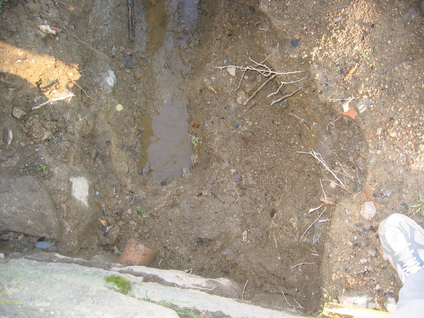
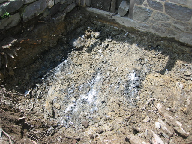
Excavation to a depth of approximately 15 inches uncovered the 1970s terra cotta drain pipe outlet exterior to the north wall near the northeast corner of the kitchen wall. This drain was set too high above the water table range and did little to reduce either the volume of water saturating mortar joints and wooden elements of the doorway or the duration of the contact of those elements with water.
A mortared aggregation of stones against the foundation is seen above and below the drain pipe in the left third of the photo. This was possibly a retaining wall, a revetment against creek incursion, or a buttress providing lateral support for the un-banked north gable wall.
Laurence Ward, 2009
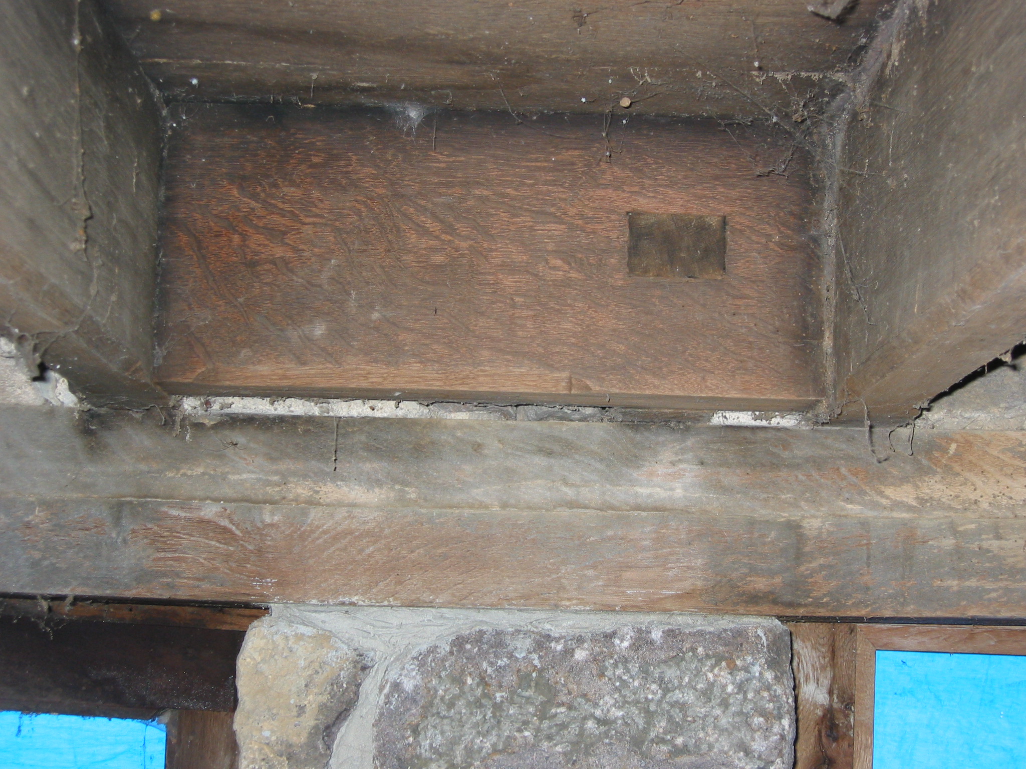
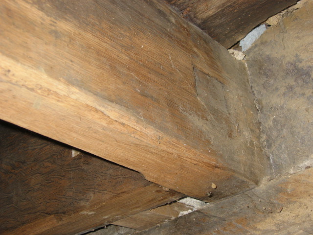
Two digital photographic images showing the anchoring header for hood outlookers above the kitchen doorway of the DeTurk House.
This "header"{1} is secured laterally into its flanking pair of first-floor joists by mortise and tenon{2} joints, indicating that a hood over the kitchen doorway was an integral part of the original construction. The end-grain of the tenon is flush with the inner surface of the header. A "pin" or "peg" driven through the wood above the mortise into the tenon stabilizes the joint. [See DTR09PH111--1001.01.207 for a detail view of this header after removal of old tenon remnant.]
The stopped chamfer terminates with a typical vernacular "lamb’s tongue", less ornately delineated than many earlier examples, {2} about an inch from the left [northern] joist, but "stops" about 4 inches from the right [southern] joist because of the framing "intersection" of the header with the outlooker through and beyond the mortise. This visual eccentricity is plausibly explained by the medieval tradition which implicitly defines "framing intersections," for purposes of locating chamfer "stops," to include a "virtual" junction of a framing member with the projected section of another member{3}.
The stacked pair of timbers across the center of the photo consists of the [upper and longer] bearing plate ["joist plate"] for the first floor joists, and the [lower and shorter] relieving lintel over the doorway and window openings of the east eaves wall in the lower ground-level kitchen. They are supported by the masonry pier [bottom-center of photo] between these openings, the masonry wall north of the window, and the pier joining the east eaves wall to the partition ["cross"] wall between the kitchen and root cellars. Similar plates are embedded in the west eaves wall and serve the same functions.
FOOTNOTES:
{1} "Anchor beam," in the British vernacular lexicon.
{2} The reduced-section projecting timber segment at an end of a framing member which fits tightly into a "mortise" [hole] in another member to structurally join the two members. The resulting mechanical connection is typically secured with wooden pegs driven transversely through the joint. A 1797 Chester County "Practical House Carpenter's Directory" uses "tenent" for this element; also "tenant" or "tennent" in the southern tier of the Mid-Atlantic colonies [Lounsbury, Illustrated Glossary of Early Southern Architecture and Landscape, Univ. of VA Press, 1999].
{3} Appearing in numerous instances throughout the framing system of this building as a simple concave ["coved"] bevel, or "splay," without beading or other decorative embellishment. The "stop" gradually returns the chamfer to the vanishing point at the right-angle edge ["arris"] of the header. For this reason, in the British tradition this form of beveled "stop" has been called a "converging" chamfer, distinguishing it from the abrupt right-angle [horizontal or vertical] chamfer terminations seen in some 17th-century English and Welsh vernacular woodwork. More finely articulated [typically with a curvilinear ("ogee") profile] versions of this expressive vernacular detail, obviously designated by its undulating namesake, appear in formal and monumental masonry structures on the continent of Europe and in the British Isles.
{4} However, such traditions were not rigidly interpreted; photo DTR09PH133--1001.01.229 shows the chamfer on the joist south of the northern outlooker extending part-way under the tenon of the anchoring header, stopping a few inches from the intersecting relieving lintel; this location of the chamfer stop apparently ignores the "intersection" of the joist with the extended section of the header through its southern tenon. An example of stopping a chamfer, with a simple beveled cove and in conformity with the joinery tradition, appears in the 2d image [Frame # 81709-929] which shows the chamfer on the lower southern arris of the first floor joist closest to the kitchen fireplace chimney breast stopped several inches before the meeting of the joist and the summer beam’s lap-joint with the fireplace lintel.
Larry Ward (2009)
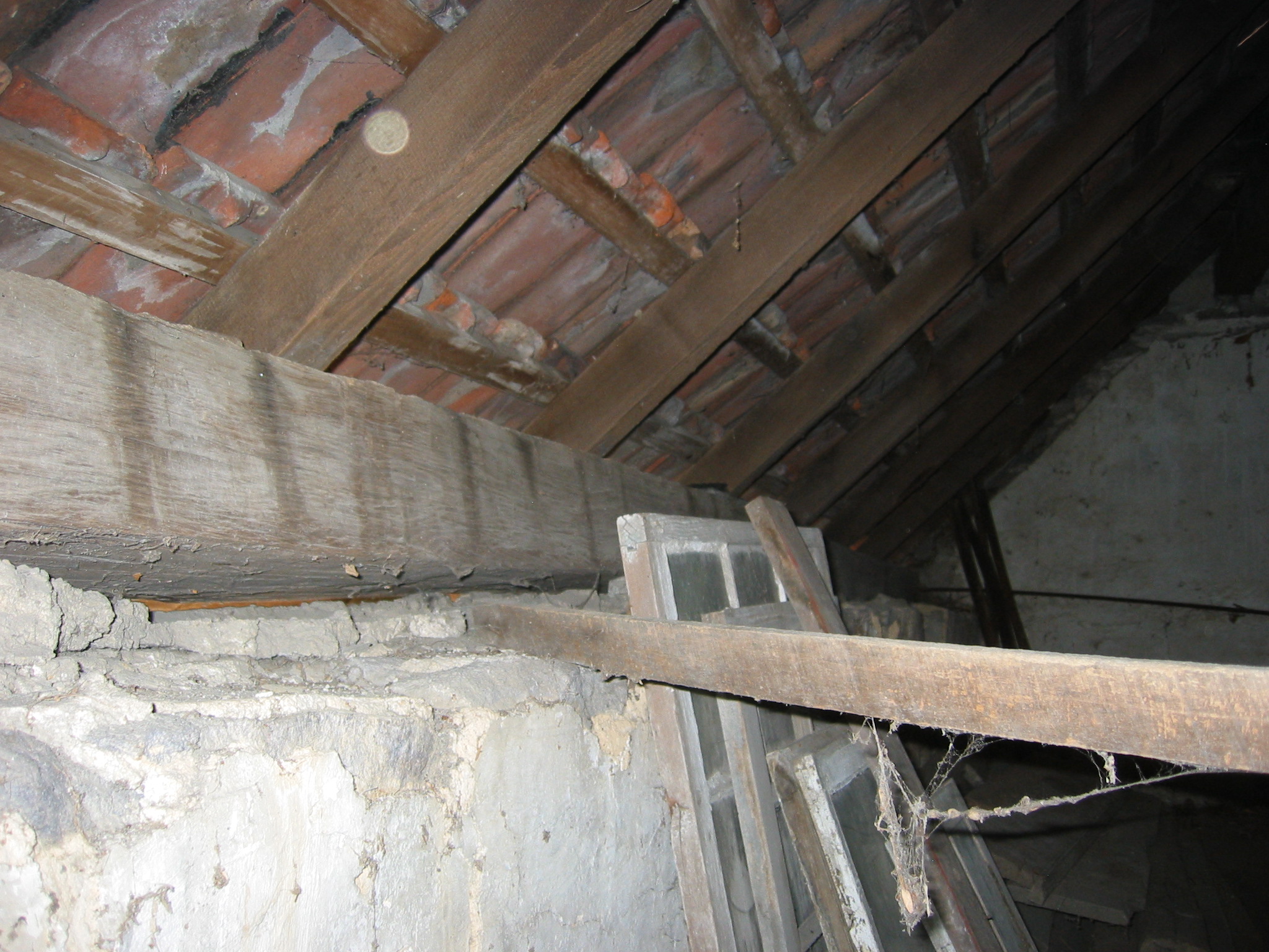
Southeast portion of DeTurk House attic granary showing east eaves wall plate [large hewn beam extending into the corner starting at the left edge of the photo]. This plate is rotated several degrees from the horizontal and curves outward, either from roof thrust or possibly because of a prior structural function, probably in another building{1}. Although insufficient "curing" [drying through evaporation] is possible as a contributory cause of the curvature, it is quite unlikely that the original builders would have installed a "green" timber for the important function of a wall plate deployed to carry the substantial loads of a roof and its timber support structure.
The roof rafters and lath were installed in the 1970s. The early clay tiles were assembled from several sources, including a group found in this 1767 building (see DTHTX18--1001.01.017 manuscript sheet headed ‘[DeTurk] Restoration Plans’ paragraph 2, which states "Enough tiles are available for the roof: 1000? Stored in DeTurk House, 1st floor, 700? Stored at Jack Keller’s farm…600? stored at Dr. German’s house (donated by Paul Blatt, Bernville)."
The iron tie rod on the right (shown more fully in the left half of photo DTR09PH102--1001.01.198) was installed in the 20th century to restrain roof thrust. This retrofit was necessitated by the inadequate integration ["tying"] of the wall plates into the structure in the original building campaign. This problem was compounded by the inability to install continuous tie beams from eaves-corner to eaves-corner because of the chimney in the north gable wall and the granary door in the south gable wall. A secondary possible cause of the partial failure of the roof support system was the replacement of lighter roof covering, wooden shingles, with heavier slate and clay tiles during various re-roofing projects on the building. This would impose substantially greater lateral thrust on the rafter plates and the masonry stone courses supporting them, tension on the rafters and their support members.
FOOTNOTE
{1} The darker vertical bands, possibly from joists bearing on this timber and reducing oxidation from exposure to air, on the inner [west] face of the rafter plate{n} might indicate prior use as a summer beam. The outward curve [which would project downward if the plate were rotated to set the bands facing upward under joists], would probably be caused by deflection of the beam from many years of load-bearing in functioning as a “summer” or girder.
{n}so called because of its primary function as the “wall” plate [generically, any timber borne on, or embedded in, a masonry wall] supporting the roof rafters and the loads they bear.
Laurence Ward, 2009, updated March 2021
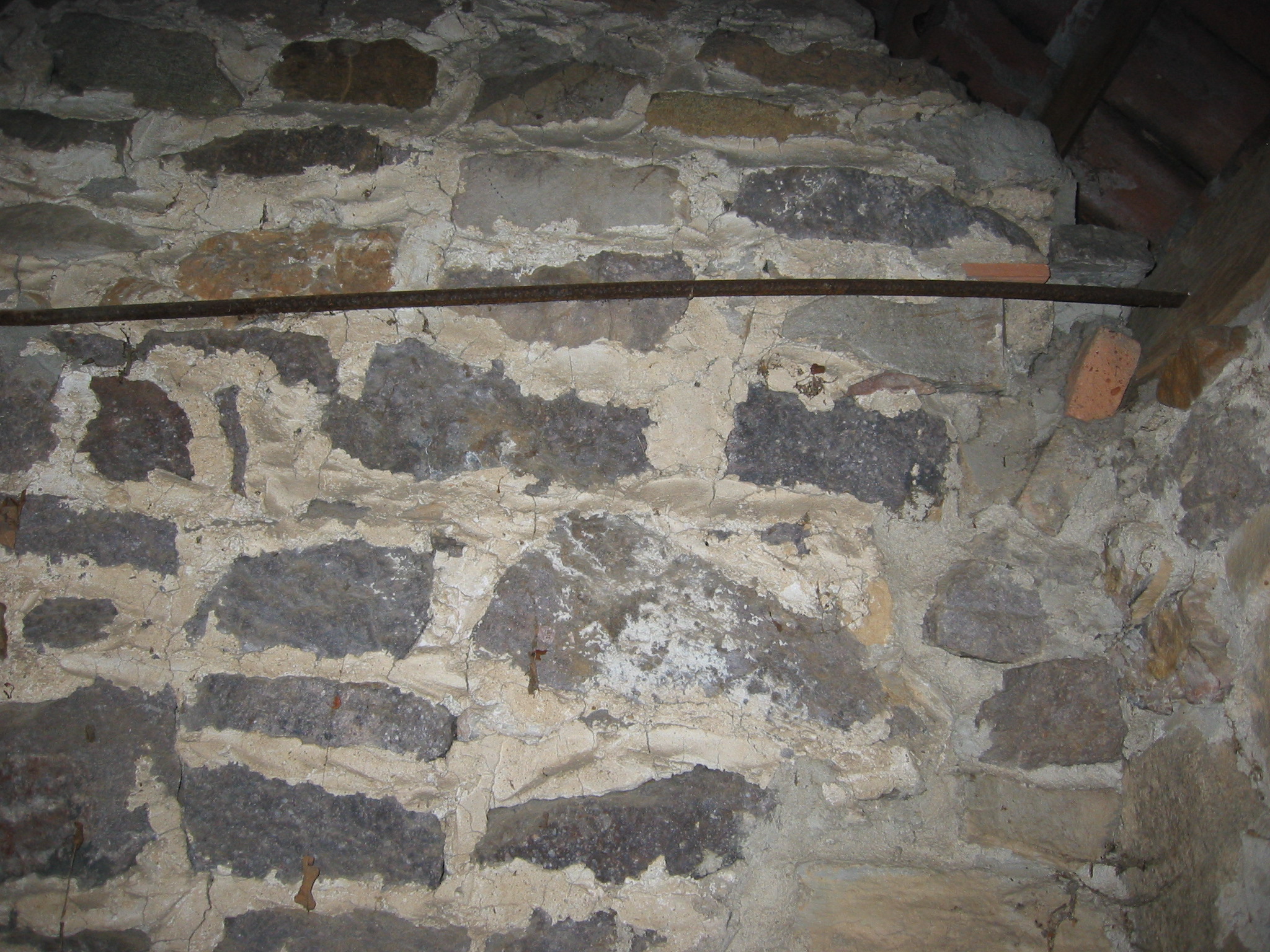
Iron tie rods were added in the 20th century as restraints against roof thrust acting on the eaves wall plates. The rod is seen entering the wall plate just below the upper right corner of the photo (the bricks are non-original in-fill). A nut secured the threaded end of the rod against the exterior vertical face of the plate. These interior rods apparently replaced exterior rods [see DTHPH7--1001.01.029] which undoubtedly became ineffective because of the rotting-out of the exposed end-grain of the wall plate securing the rod spanning the north gable at the eaves level.
Laurence Ward, 2009
Iron tie rods were added in the 20th century as restraints against roof thrust acting on the eaves wall plates [“rafter plates”]. This pair in the north gable are secured by threaded nuts on the exterior face of the wall plates, and by embedding the interior terminals in mortar joints [seen to the left in this photo]. These interior rods apparently replaced an exterior rod [see DTHPH7--1001.01.029] which undoubtedly became ineffective because of the deterioration of the exposed end-grain of the wall plate securing the rod spanning the north gable at the eaves level.
The gray mortar at the anchor-point is essentially modern “Portland” cement, not a traditional lime-sand or lime-clay mix which would have been applied in the earlier periods of the building.
Laurence Ward, 2009
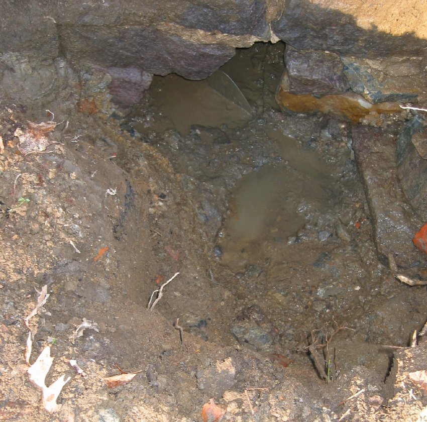
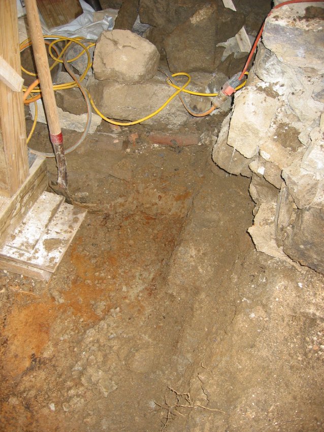
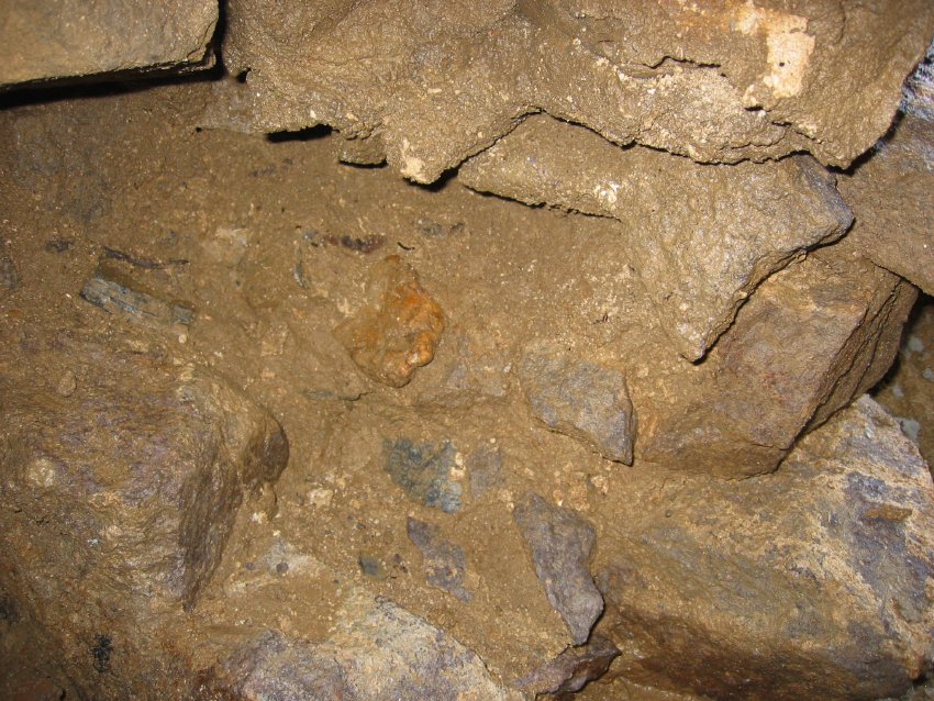
Partially excavated DeTurk cellar floor drain outlet.
The stone at the right edge of the photo is slightly angled toward the creek, at the same angle relative to the east wall as the jamb-stones of the drain are within the "tunnel" through the wall [see DTR09PH80--1001.01.169, DTR09PH78--1001.01.167, and DTR09PH82--1001.01.171]. The trowel blade in the upper-center of the photo is in contact with the bedrock floor of the drain.
Laurence Ward, 2009
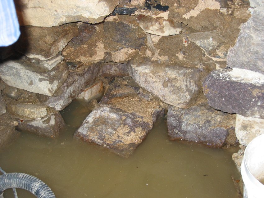
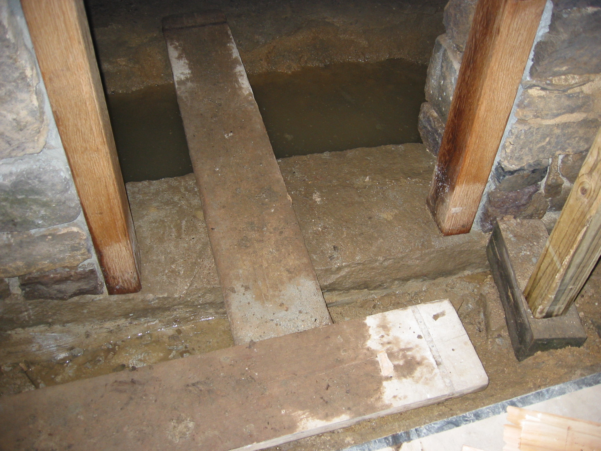
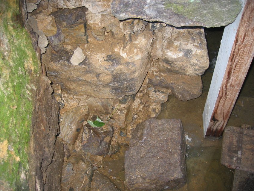
Inlet of original cellar kitchen floor drain through east wall foundation, prior to restoration.
Excavation in December, 2009 uncovered the 18th-century kitchen-cellar drain [see DTR09PH80--1001.01.169 (pre-restoration) and DTR09PH82--1001.01.171 (restored)], basically a tunnel [rectangular in section at its inlet] on bedrock passing through the east wall foundation, slightly skewed toward the creek, between the kitchen window and the northeast corner of the building. The upper chamber of this tunnel will be enclosed with a 6-inch pipe, "mudded in" to prevent infiltration of exterior ground water. This will achieve positive drainage when the water level in the cellar is higher than the creek, while preventing backflow when the creek is higher by means of a hydraulic check valve near the outlet.
Cut faces of north jamb of drain are seen to the left of large block in water. Other stones have shifted or fallen from original positions because of degradation of mortar from long term saturation of soluble ingredients.
Laurence Ward, 2009
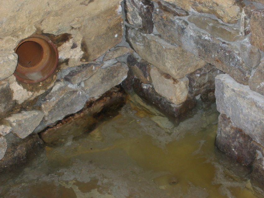
Restored floor drain inlet through east foundation wall of kitchen. See DTR09PH14--1001.01.095 for a pre-restoration view of this corner.
The bottom of the 6-inch PVC pipe inserted in the upper half of the rectangular drain tunnel is 8 inches below the door sill [2 inches lower than the restored floor level will be]. The pipe will drain the kitchen floor when the creek level is lower than the water level in the kitchen, provided the water level in the kitchen is no more than 8 inches below the sill.
It is expected that this drain, in conjunction with the dual channel-drain system to be installed in the stairwell outside the kitchen doorway, will lower the water table inside and outside the door sill by 6-12 inches within hours after heavy rain ceases and the creek recedes. Under conditions preceding these installations, the water table receded as little as 1 inch [or less] per day {1}, depending on the degree of saturation of the surrounding watershed.
Back-flow will be controlled by a check valve at the outlet of the pipe. Setting the drain inlet any lower than this would create reverse ["negative"] pitch to the outlet elevation at the bottom of the pipe.
The terra-cotta pipe through the north wall was installed in the 1970s to drain the modern kitchen floor, which was 18-24 inches above the original [ to be restored] brick-paved floor elevation, too high to reduce saturation of the lower foundation wall and its mortar joints.
Provision will be made to install an emergency sump-pump in the northeast corner segment of the sedimentation trough to drain the cellar in extreme flooding conditions. A sleeve will pass through the existing terra-cotta pipe in the north wall [upper left quadrant of photo] for the outlet hose from the pump.
This photo also shows the restored foundation walls converging at the northeast corner of the kitchen, now plumb, re-mortared, and stabilized. This restored stonework was repointed in April, 2010 using hydraulic mortar below the high water-table level.
The Left jamb of the early drain is 10 inches from the northeast interior corner. The right edge of the terra-cotta pipe is 14 inches west of the same corner.
The darker stones at water level are the base blocks of the foundation and are set on a leveling layer of sandy clay on limestone bedrock, which provides a stable natural "footing" for the masonry wall system {2}.
FOOTNOTES
{1} Numerous photos and water table level readings taken between July, 2009 and April, 2010 clearly demonstrate the slow rate of percolation of ground water accumulations away from the building and into the creek.
{2} Less than two miles south of this building the working face of a limestone quarry is over 400 feet high.
Laurence Ward, 2010
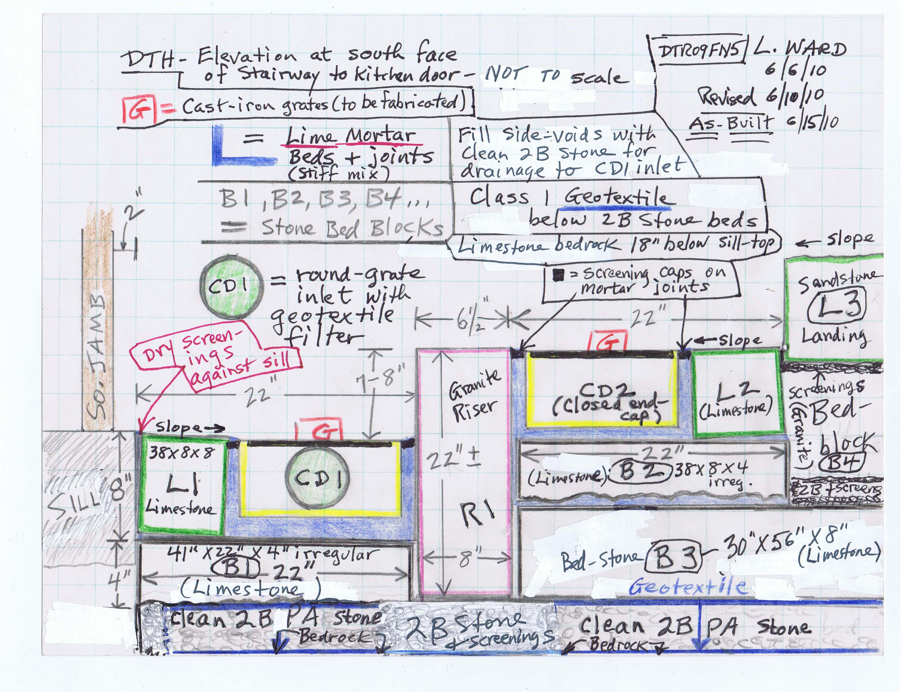
South elevation detail sketch drawing of June, 2010 installation of stone staircase and channel drains at DeTurk House kitchen-cellar entry.
See DTR09PH134--1001.01.230 for photographs of this installation.
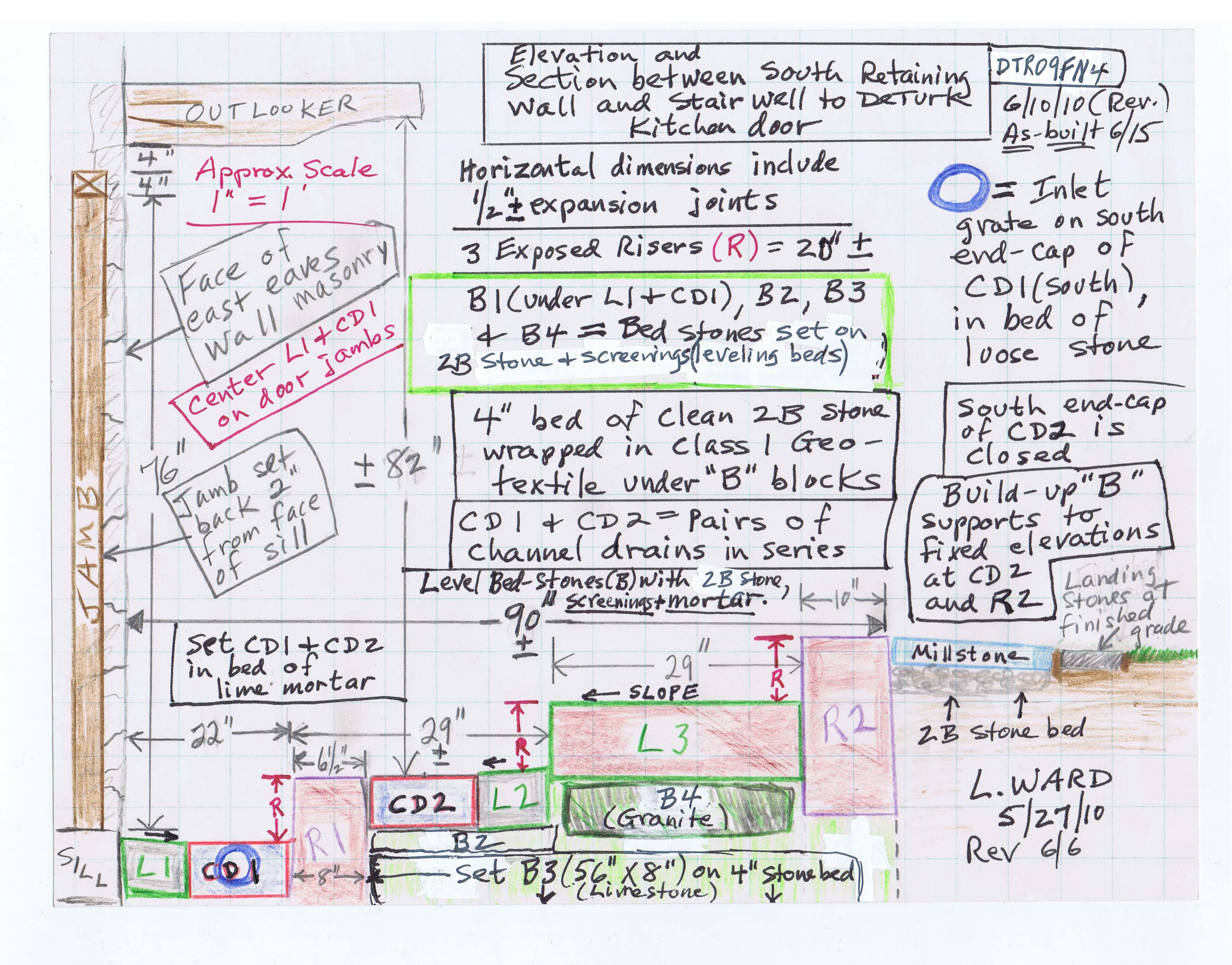
South elevation sketch drawing of June, 2010 installation of stone staircase and channel drains at DeTurk House kitchen-cellar entry.
See DTR09PH134--1001.01.230 for photographs of this installation.
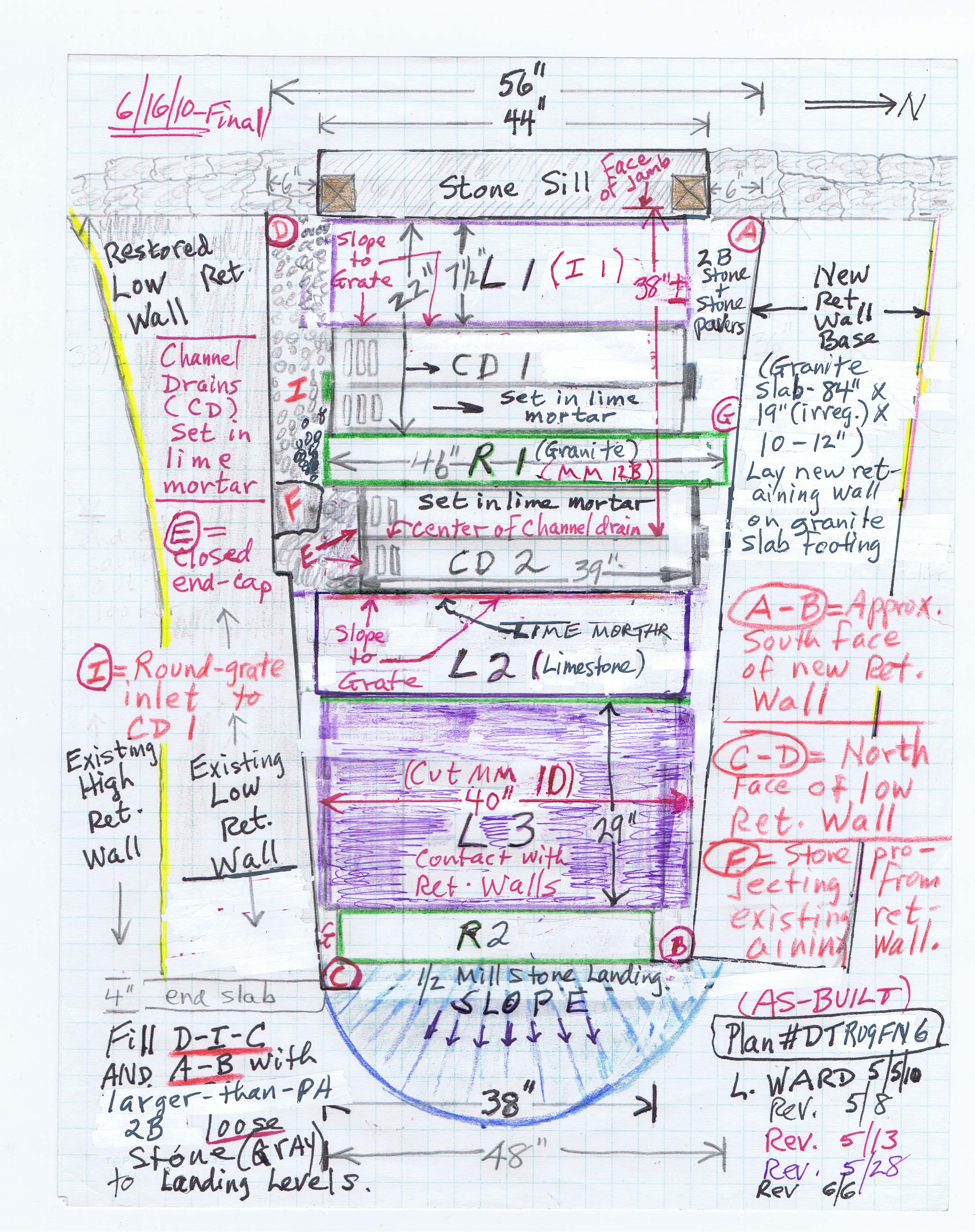
Sketch plan drawing of June, 2010 installation of stone staircase, north retaining wall, and channel drains at DeTurk House kitchen-cellar entry.
See DTR09PH134--1001.01.230 for photographs of this installation.
Series of 32 digital photographs showing the construction of the exterior stone steps to the lower-grade level kitchen doorway at the DeTurk House. Full captions for numbered photos appear below.
June 14, 2010
2634: Brittle top layer of limestone bedrock found 18" below top of door sill.
2635: Chipped and fractured bedrock stratum under door sill.
2636: White-veined blue limestone bedrock at bottom of excavation for staircase. This is the same [Dolomitic] limestone under most of the Oley Valley; in a quarry about 2 miles to the south, where the “table” of stone is about 400 feet thick to the base of the quarry face.
2637: White-veined blue limestone bedrock at bottom of excavation for staircase.
2638: Sizing and cutting geo-textile filter fabric for stone-bed underlayment.
2639: Geo-textile fabric covering bedrock.
2640: Loading "2B" clean stone onto geo-textile fabric.
2641: Leveling 2B stone bed.
June 15, 2010
0001: Rubber-tracked Kubota 161 Mini-Excavator mobilized to excavate, set bed-stones, step-blocks, landings, and risers forming the staircase.
0002: Lower limestone landing ["L1"-see Field Notes sketch-drawings DTR09FN4--1001.01.231 & DTR09FN5--1001.01.232], which is 41inches x 22 inches x 4 inches, set on irregular ("rock-face") limestone bed stone ["B1"] to support L1 [lower landing, against sill] and CD1 [lower channel drain, at same elevation as L1].
0009: 30 inches x 56 inches x 8 inches limestone bed-stone ["B3"], positioned as shown in DTR09FN5--1001.01.232 to provide continuous solid support from bedrock upward through bed-stones, which bear step-blocks ["landings"], risers, and channel drains.
0016: L1, R1 [granite riser] & B3 set in final alignment on 2B stone and screenings leveling bed, and CD1, set in a lime mortar bed with mortared [vertical] side-joints capped with screenings.
0017: 360 degree leveling laser used to set elevations of landings and channel drain grates, using top of sill at north door jamb as reference datum.
0019: 38" x 22" x 4" with one of its larger surfaces on (irregular "rock-face") limestone bed stone ["B2"] to support upper limestone step-block ["L2"] and CD2 [upper channel drain].
0020: setting B2.
0023: setting and leveling B2 on stone screening bed.
0026: setting and leveling L2 on stone screening bed.
0030: Grappling granite bed-stone [ "B4", 38" x 22" x 8"] into position, with 2-plate "thumb" attachment, to support sandstone landing ["L3"], which is 40" x 29" x 8".
0031: Transporting B4 down embankment to staircase excavation.
0032: Preparing to set B4 in place.
0033: screenings bed leveled to receive bed-stone B4.
0037: B4 in place and leveled on screenings bed.
0052: L3 grappled with excavator bucket and "thumb" to its site.
0054: leveling L3.
0058: Setting mortar bed for CD2.
0063: Troweling mortar into joints flanking CD2.
0064: Screening caps on channel drain mortar joints.
September 7, 2009
1084: East eaves wall detail and kitchen doorway prior to completion of staircase, retaining wall, and drains protecting doorway and foundation walls.
July 3, 2010
104: East eaves wall detail and kitchen doorway after completion of staircase, retaining wall, and drains protecting doorway and foundation walls
Laurence Ward, 2009, UPDATED Oct 2021 and September, 2022
Detail photo in DeTurk kitchen showing the "stopped" chamfer [see footnote {2} in DTR09PH119--1001.01.215] on the original first floor joist south of the northern outlooker; the chamfer on the southern edge ["arris"] of the joist extends part-way under the tenon of the anchoring header, stopping a few inches from the intersecting relieving lintel, apparently ignoring the "intersection" of the joist with the extended section of the header through its southern tenon. The chamfer on the header [see DTR09PH119--1001.01.215], by contrast and apparently honoring the tradition, stops before reaching the "virtual" intersection with the extended section of the tenon of the northern outlooker [the cantilevered support for the doorway hood]. The outlooker appears in the lower center of the photo bearing across the upper relieving lintel spanning the kitchen window and doorway.
Laurence Ward, 2010
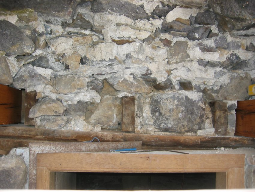
View of wall above kitchen door after removal of exterior layer [“wythe”] of stones, which were distended and out of plumb.
Stones removed from above the doorway were laid out on the ground in "mirror" position and were re-laid and "mudded in" [set and bonded in bed and joint mortar] in their original positions. Repointing of this wall segment was completed in April, 2010, using a traditional lime-mortar mix consisting of lime, water, and sand “aggregate” from the nearby Little Manatawny Creek.
Details shown include the replacement door-frame lintel; the "stacked" pair of bearing plates; end grain of three original floor joists; original bonding [also "bed" or "setting"] mortar and the "keyed" inter-positioning of stones of various sizes, shapes, and setting angles characteristic of random rubble masonry; filleted corner ["quarter round"] bead along jamb and lintel edges ["arrises"]; and a portion of the replaced outlookers emerging from wall [reddish-brown wood surfaces at right and left edges of photo]. Also apparent is the 2-inch deflection of the paired "wall plates," the upper member bearing the joists, now deflected from south to north [left to right] across the photo partially behind the carpenter's square, which is level.
See DTR09PH92--1001.01.184, a series of 18 photos showing the removal of these stones above the doorway as well as a reconstructed view prior to repointing.
Laurence Ward, 2009, updated March, 2021
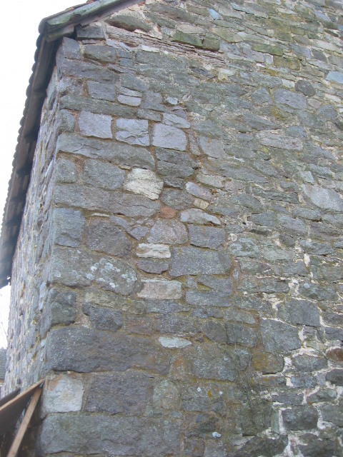
The jagged vertical crack descends from just under the joint between the east wall plate [upper left corner of photo] and the weathered horizontal oak plate tie extending 4 feet westward from the wall plate at the eaves level {1}. The darker pointing in the re-built north wall segment is left [east] of the crack in the photo, and the earlier [lighter colored] pointing to the right of the crack defines the un-restored portion of the wall{2}.
The alternating long stones at the corner of the north and east walls are sometimes called "quoins" [anglicized to "coin" in the 19th century], which compressively bind ["tie"] the vertical mortar joints close to the corner.
See an interior view of this repaired crack and the contrasting pointing in the wall ranges flanking the crack in DTR09PH95--1001.01.187
FOOTNOTES:
{1} See discussion to DTR09PH93--1001.01.185.
{2} See drawing DTHDWG1--1001.01.045 cited in footnote {3} of DTR09PH69--1001.01.153 showing the location of the crack in the "basement" plan view, with a note stating that the displaced wall "moved + or - 6 inches." According to drawing DTHDWG1--1001.01.045, this "tectonic" event in the random rubble gable wall forced the eastern corner segment of the north wall toward the west, partially over-riding the wall-range west of the crack. This through-fracture was repaired and the corner piers of the intersecting east and north masonry walls were relaid in the 1970s.
Laurence Ward, 2009
Exterior view of north door jamb foot in one inch of water above stone sill after 2 inches of rain in 36 hours.
This water level would submerge the restored brick-paved kitchen floor under seven inches of water and place the foundation wall and its exposed mortar joints in contact with more than one foot of standing water, which recedes from that level very slowly by natural percolation through the soils, wall pores, and limestone bedrock. The restored original drain tunnel, with an enclosed and backflow-protected gravity drainage course, will discharge these water levels in a fraction of the elapsed time required in the absence of these facilities, and will significantly reduce both the duration and extent of these incursions. This system will substantially extend the life expectancy of the pointing and bonding mortars, materially prolonging the durability of the masonry foundation.
Laurence Ward, 2009
Detail view of jamb [top-center], door sill [upper center], and retaining wall blocks (left third of photo), [detail at lower left corner of DTR09PH51--1001.01.135].
Blocks along left third of photo are foundation stones of the low retaining wall and masonry abutment south of the kitchen doorway before restoration [see DTR09PH61--1001.01.145 for restored view of this abutment, and DTR09PH125--1001.01.221 for a view of the relaid low retaining wall abutting the higher retaining wall to its south.]
Laurence Ward, 2009
Exterior view of restored [original] kitchen door sill and lower portions of replacement oak jambs. The [original] stone sill was shifted 2-3 inches to the right [north] to accommodate the adjusted jamb alignments [see DTR09PH4--1001.01.124 for discussion of the effects of this relocation of the sill on the relationship between the doorway jambs, lintel, sill, abutments and hood outlookers, and DTR09FN3--1001.01.176 for a field notes drawing of the probable historic and modern locations of those elements].
See discussion to DTR09PH60--1001.01.144 regarding the water table inside and outside the stone sill and necessary mitigation plans (see DTR09PH66--1001.01.150) designed to protect the structure from its effects.
Masonry abutment piers were re-pointed with locally formulated mortar in 2010, applying a hydraulic-grade mix to joints below finished grade or below the high water table range.
Laurence Ward, 2010
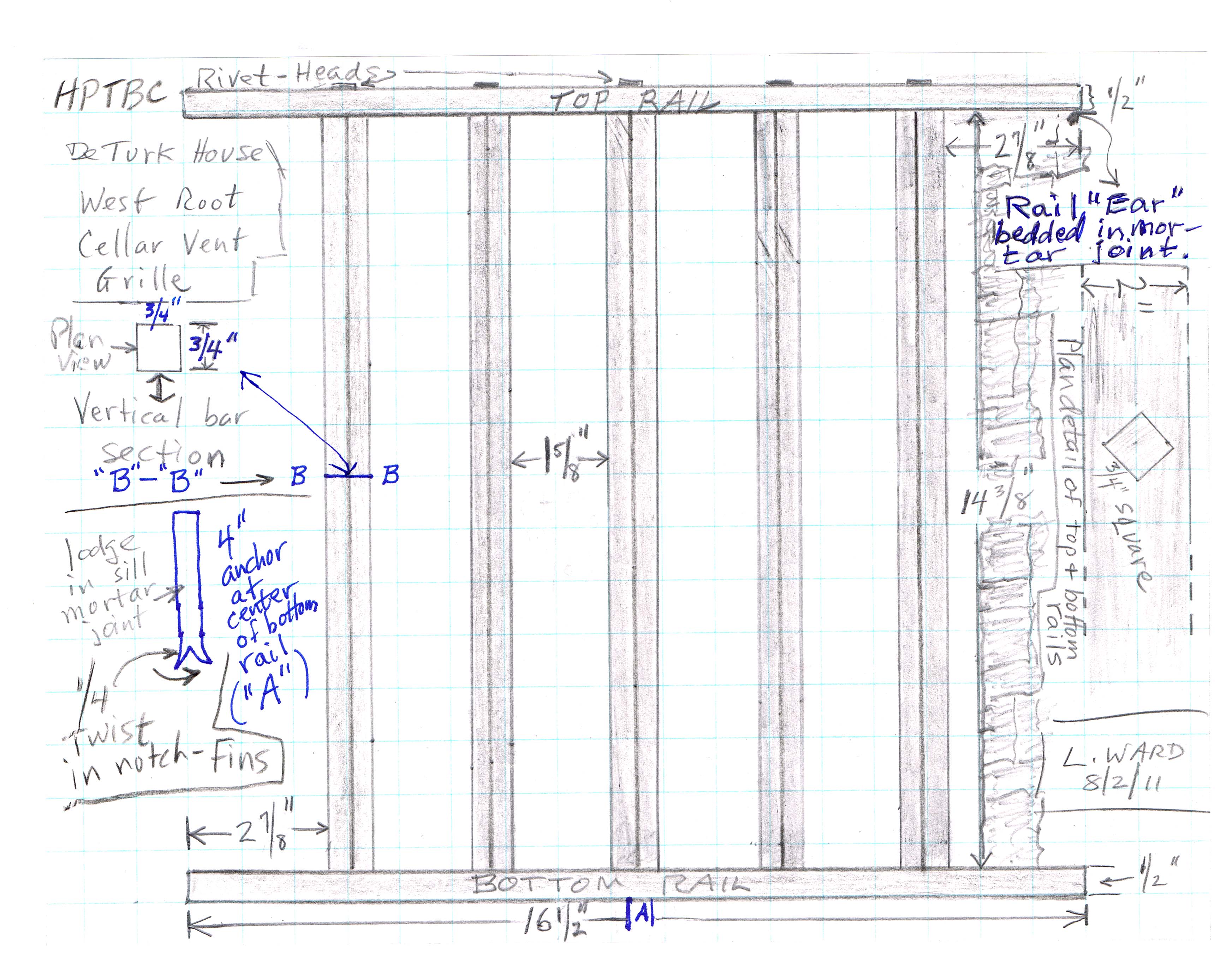
Series of three images (one digital copy of a field notes drawing by L. Ward and two digital photographs) showing the vent grille used by blacksmith James Kieffer of Honey Brook, Chester County, PA, to fabricate the grille to the precise dimensions of the vent opening in the west wall of the root cellar, and the re-fabricated grille. The grille was installed in the fall of 2011 by restoration mason Joe Forrest, who also laid the stone sill supporting the replacement grille. The milled steel rails and bars were cut to the specifications in the drawing and secured with the "fish-tail" anchor set into the mortar joint located in the center of the new sill, which rises above the disintegrated sill by approximately five inches. The vertical bars are aligned on the diagonal in the traditional manner to allow more light into the root cellar without reducing the volume of air vented through the grille.
Also attached is a photo of the grille after installation [Image #2].
Image three is of the previously existing early [possibly original] grille in the vent opening in the east wall of the root cellar. This grille was used as a template for the replacement grille, modified slightly to fit into the existing opening.
Laurence Ward, 2011; updated, March, 2021
Detail of DTR09PH70--1001.01.154, showing displaced foundation stones under kitchen window.
The primary structural problem in this small building, dramatically evident in the sandy-mud mortar-residue visible in the lower-right quadrant of this photo, was the debilitating long term effects from saturation of mortar and the consequent dissolution of much of its lime ingredient. This process resulted in loss of the primary bonding agent in the "pre-Portland" era {1}, producing an unstable, overly compressed, and inelastic mixture, unable to maintain the compressive bond in the masonry wall or to prevent lateral and diagonal displacement in parts of the structure. Lower foundation blocks in the excavated area are darkened by frequent saturation of kitchen-floor fill by runoff infiltration, high water table, and occasional creek flooding. All three sources will be addressed in the drainage and diversion plans discussed in DTR09PH74--1001.01.163 and DTR09PH66—1001.01.150.
FOOTNOTES
{1} Undersized or otherwise deficient or misaligned bond timbers and wall plates, the use of truncated eaves plate ties in place of true tie-beams to restrain roof thrust, the use of joists laid flat in place of embedded wall-beams of deeper section, and other framing "shortcuts" might have been additional contributing factors in the manifold structural failures, especially the long "lightning-bolt" crack discussed in note {3} to DTR09PH69--1001.01.153 [see also DTR09PH93--1001.01.185, DTR09PH94--1001.01.186 and DTR09PH95--1001.01.187 and related photo descriptions and discussion] and other dislocations and fractures documented by numerous photos in this archive.
Laurence Ward, 2009
Detail view of degraded kitchen foundation wall during restoration.
View from inside kitchen under window, rotated 90 degrees northward from DTR09PH71--1001.01.155, showing extent of mortar disintegration within the wall.
Laurence Ward, 2009
Exterior masonry pier south of replacement door jamb (white primer paint on south face) at kitchen doorway.
Displaced stones have been removed to allow relaying, consolidation, and stabilization of pier stonework, restoring a plumb alignment with the door jamb. Green stones along left edge of photo are face blocks of the east-west retaining wall intersecting this pier.
See DTR09PH61--1001.01.145 for restored perspective view of this pier and the lower segment of the retaining wall as well as a restored view of the south abutment; see DTR09PH54--1001.01.138 for a restored view of the north abutment.
Laurence Ward, 2009
.
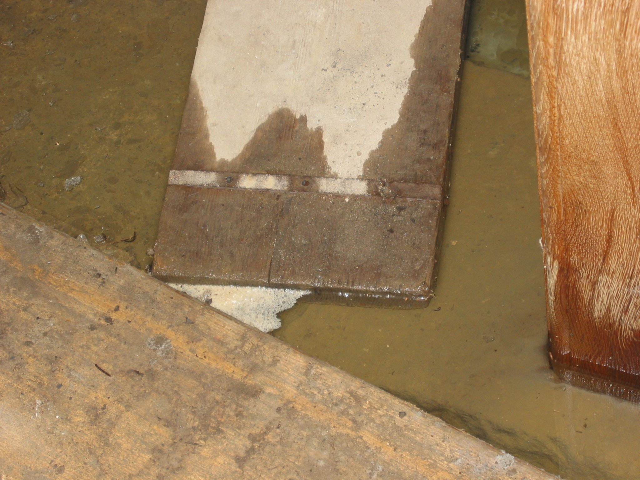
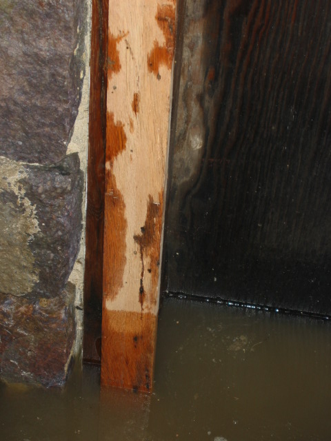
The replacement southern jamb at the ground-level kitchen doorway stands for days in the water which covers the stone sill, on which the jambs are anchored by iron pins in mortises chiseled into the sill. The darkened area of the jamb above the water level has been soaked by the high water table and "wicking" of water upward in the porous oak timber. This prolonged saturation initiates the cycle leading to rot in timber members, necessitating the mitigation measures referred to in DTR09PH98--1001.01.190, DTR09PH66--1001.01.150 , and DTR09PH74--1001.01.163. See DTR09PH96--1001.01.188 for a discussion of the effects and remedies regarding this persistently high water table.
Laurence Ward, 2009
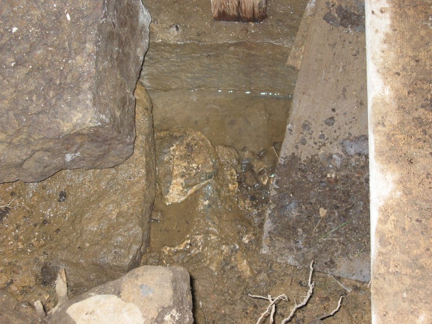
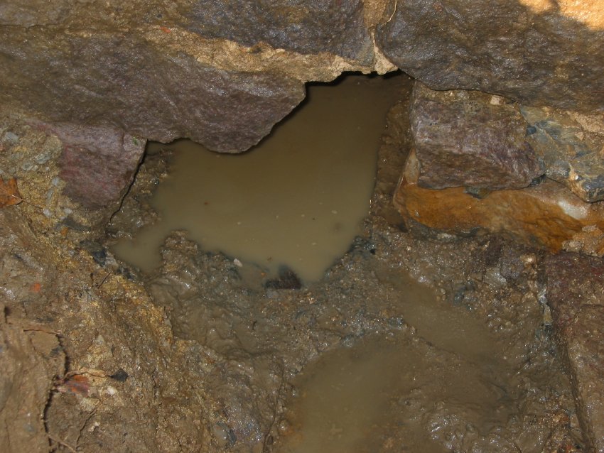
Detail of DTR09PH77--1001.01.166 showing exterior view (outlet) of partially excavated exterior aperture of drain tunnel.
The bedrock floor of the drain tunnel was evident under the pool of water in the masonry opening at a depth [“invert”] of approximately 18 inches below the sill elevation, the same level as the bedrock encountered at the base of the excavation for the exterior stone stairs to the ground level kitchen doorway. This bedrock formation appears to be related to the same type of white-veined blue limestone being quarried [to a depth of over 400 feet from the surface] less than 2 miles south of the DeTurk site.
See DTR09PH84--1001.01.173 for restored and modified drain outlet. See also DTR09PH80--1001.01.169 for interior view (inlet) of same drain tunnel aperture.
Laurence Ward, 2009