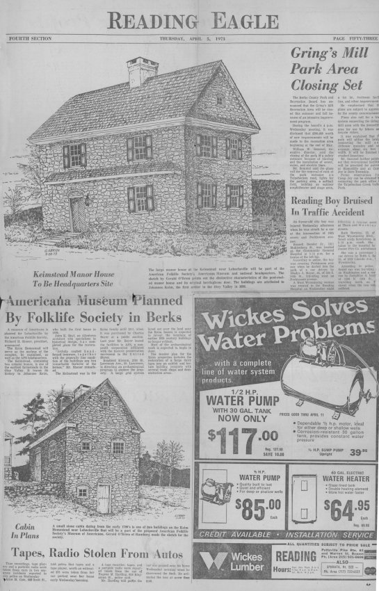
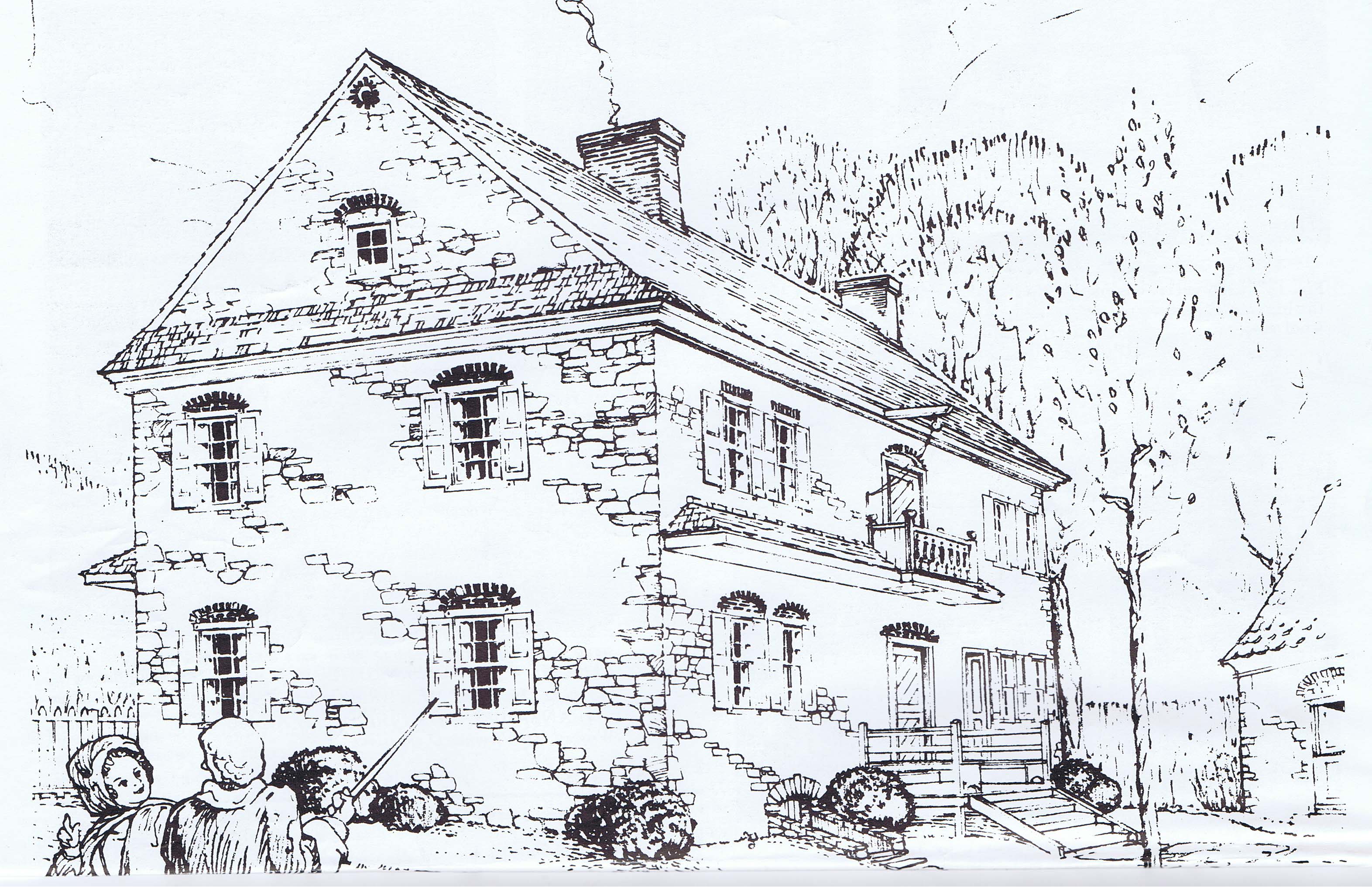
Half-page article with drawings (by Gerald O'Brien) from the Thursday April 5, 1973 edition of the "Reading Eagle." Article appears on page 53, Fourth Section.
Article briefly discusses American Folklife Society's (owner of Keim farmstead in 1973) plans for converting the Keim farmstead into a history museum & national headquarters site.
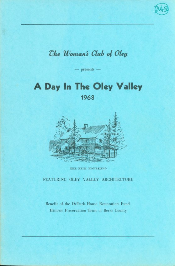
Ten-page booklet (6" w x 9" h) outlining a driving tour of the Oley Valley arranged by The Woman's Club of Oley.
Features include: map, one-page introduction, brief histories for seven sites, and acknowledgements of property owners and tour committee members.
The Keim Homestead is the second site featured. Brief historical text for Keim Homestead begins on page 4.
Full text of bookelt can be found under additional images or MULITIMEDIA LINKS.
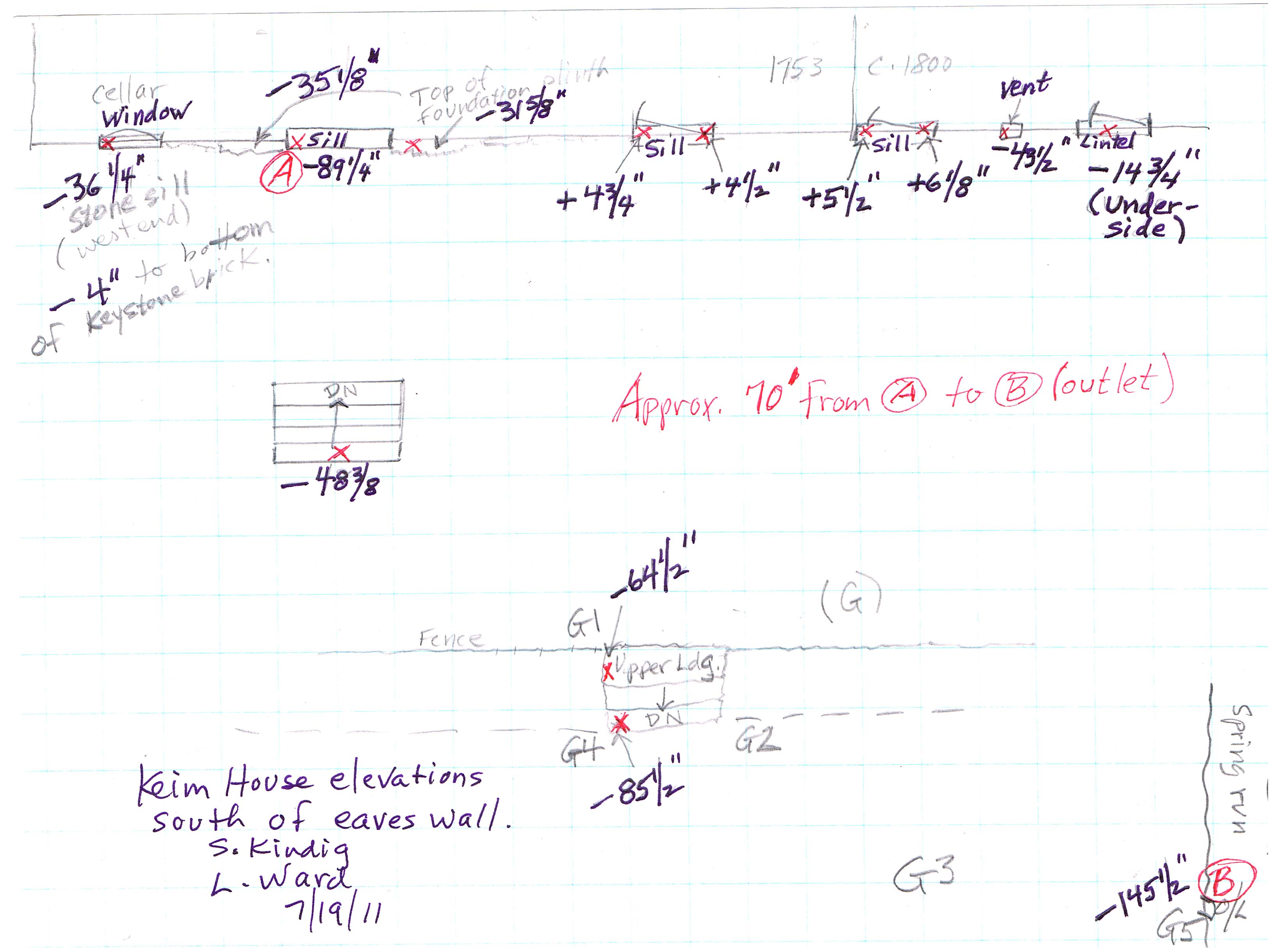
Keim House, field notes drawing, elevations South of the Southern eaves wall (2011). Digital image #1 is a Field Notes drawing showing the Keim House grade elevations south of the south eaves wall.
Description:
The data recorded on this sketch [together with future archaeological investigations] will provide guidance for determining the early and restored objective grades of the terraced yard area bounded by the 1753 house, the c.1800 addition, the mid-18th century "ancillary" wood-turner's shop building, and the low stone retaining wall separating the yard from the grass area north of the barn. The resulting data, in conjunction with soils strata and the degree of their disturbance, will possibly aid in determining the relative pre-and post-construction grades and the existence or non-existence of masonry supports for early entry structures at the 1753 and federal-era doorways. No such foundation remnants have been discovered as of 2015. This information will also facilitate the planning for surface drainage to be controlled by the final slopes, swales, and contours established for the terraced ground area and the contiguous inclined grade to the barn. Under early tradition and Common Law, these living and work areas adjacent to the house and principal dependency buildings have been called the "curtilage", and have been endowed with a privacy aspect for the occupants.
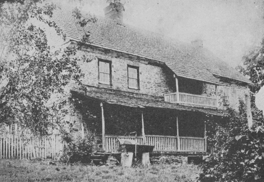
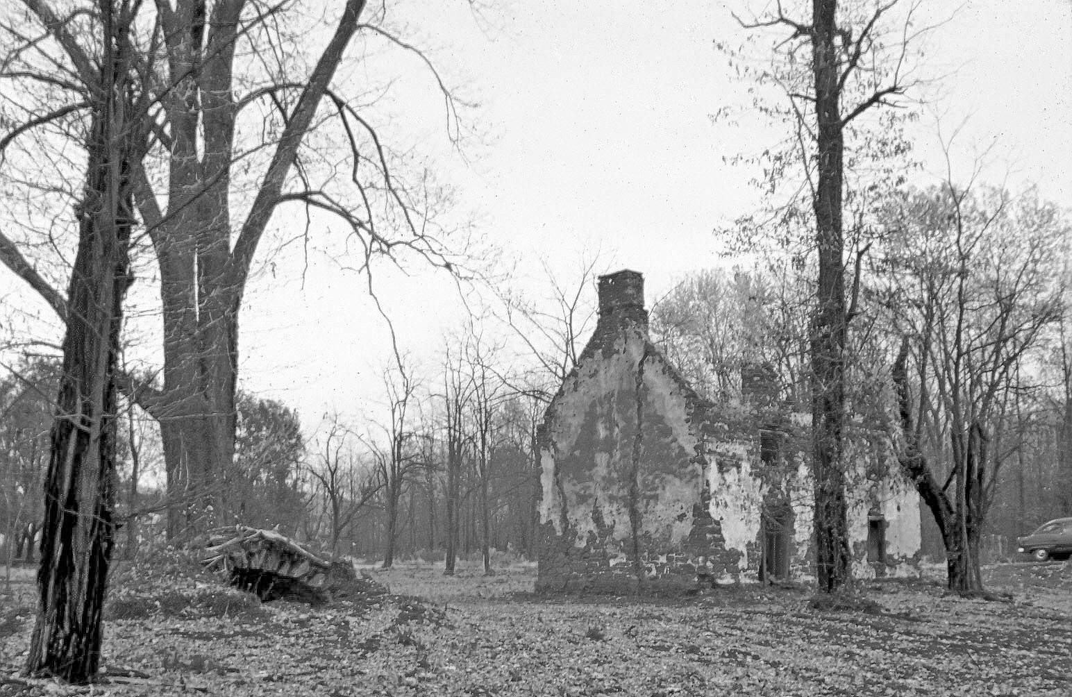
The wall and stone steps leading from the terrace to the barnyard were probably created in the 2d quarter of the 20th century (prior to the 1941 HABS photo in these archives), contemporaneously with construction of the two-wall porch that is depicted in archive record KHPH9--1002.01.044. Image #2, a photo taken c. 1929-1931 by Amandus D. Moyer, confirms the absence of a porch structure on the western gable wall as of the photo's date. The Moyer photo provides some indication of the early 20th century grades and slopes.
The early grade along the building is delineated by the top of the foundation plinth{1} which was concealed during the past century by the stone piers supporting the porches and the overfill of incoherent soils and small stones under the c.1930s porch (removed in 2011).
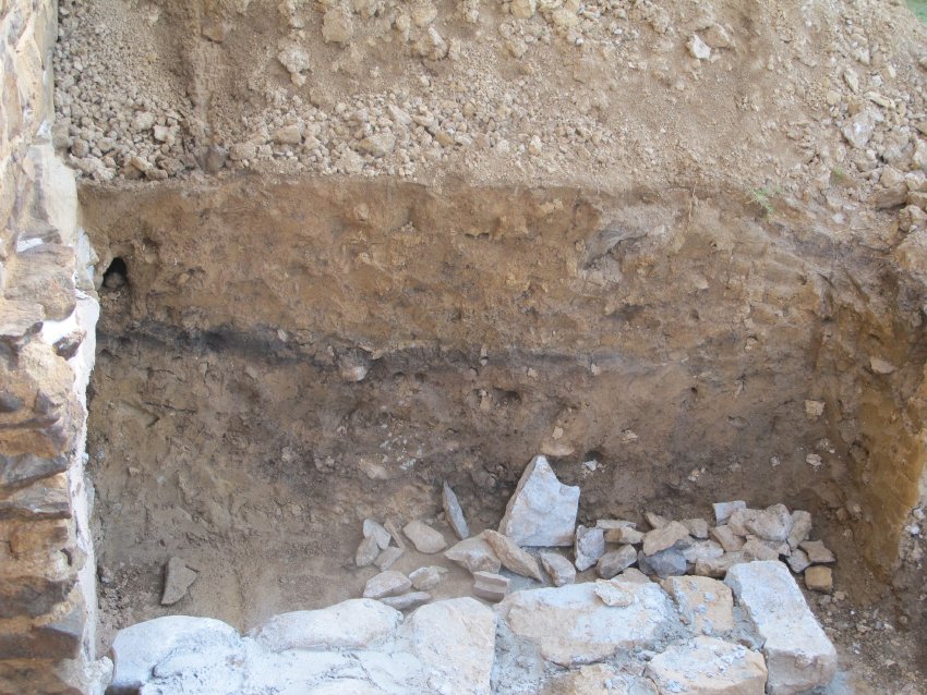
A stratum of dark top-soil a few feet below the present grade (which aligns with the top of the plinth) indicates that the post-construction (1753) grade was probably established by depositing sandy clay, probably excavated from the cellar space or from elsewhere on the farm, on top of the pre-construction topsoil.
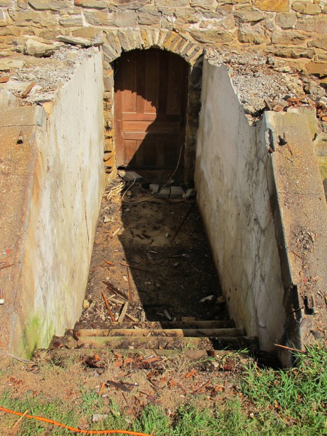
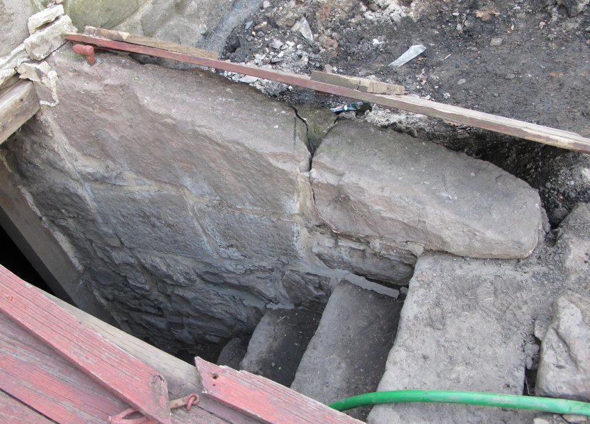
The drawing in this record provides the plinth elevations on each side of the cellar entry opening [the east plinth is about 3.5 inches higher than the west]. These levels and the depth ["invert"] of the cellar doorway sill were the benchmarks which provided the relative elevations of the reconstructed stone retaining walls flanking the "cellarway" consisting of the stone steps and passage through the foundation wall [see record # KR11PH1].
The elevations recorded on the drawing and the point-to-point dimensions noted also indicate the appropriate pitch and run of the swales, contours, and topography of the surface drainage courses from the foundation, the roof runoff drip-line, and the perimeter-line of the retaining walls. All these grade contours are sloped toward the absorption area north of the barn and the margins of the spring-run south of the "ancillary" wood-turner's workshop building [see photos in record KR11PH2--1002.01.088]. These data could also provide a rational basis for future re-establishment of a close approximation of the grades south of the early farmstead buildings.
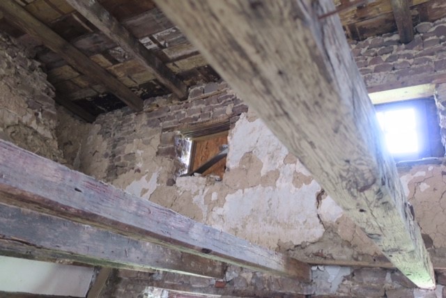
The elevation data also provided a mathematical framework for the constructive geometry and dimensions of the "cellar-cap" door and frame which would have spanned the retaining walls and sheltered the cellarway{2} passage; see archive record KR11PH1--1002.01.087 for commentary and photographs describing the reconstructed cellar entry-way, the probable form of early "cellar doors" [see the 1786 Rules of Work of the Carpenters' Company of the City and County of Philadelphia] which sheltered this opening, and the hypothesized "bulkhead" framing and sides ["cheek-walls"] which supported the angled and "hung-double" doors{3}.
The re-created retaining walls serve the dual functions of bearing the cellar doors and their support structure, and restraining the lateral soils and hydrostatic pressure from intruding into and jeopardizing the stairwell.
FOOTNOTES
{1} The base-wall ["footing", in modern terms; "basement" in neo-classical terminology] projecting beyond the plane of the wall it supports. This foundation segment, coarser in its irregular exterior plane than the "random rubble" contours of the above-grade walling, delineates the below-grade portion of the foundation. The plinth is thicker than the upper wall ranges, providing a structurally advantageous "basement" [the structural masonry perimeter supporting the building's superstructure and enclosing the cellar], and is not laid with a plumb face-plane or finish pointing, since it was not expected to be seen. It is quite possible that this segment of the foundation walls was laid from inside the cellar excavation, eliminating the need for pointing the exterior face of the plinth. The durability of the walling thus depended on "deep-pointing" the beds and joints from the interior of the cellar, rather than the more common practice of bedding and bonding ("mudding-in") the foundation stonework from both sides of the foundation, and often laying-up the exterior walls from a "builder's trench." Assuming that the base-stones are footed on a solid bearing sub-strate [on the Keim site, a dense amber-colored clay], both construction techniques provide a stable bearing system to carry the compressive load imposed by the massive super-structure of the masonry and timber-framed 1753 dwelling.
The top ["coping" or "water table"] of the plinth descends from west to east, delineating the final desired grade established as described above, and disappears as the grade along the wall falls toward the stone sill below the cellar doorway in the Federal-period addition. See the top of the "rubble" plinth in Image #3 [flanking the cellar doorway opening].
{2} Although a door could have been fastened to the interior abutments of the arched opening with pintles ["hooks", in 18th century terminology], no evidence has yet been found "documenting" a door frame attached to the arched masonry opening or joined to the joisted framing system above the cellar cavity enclosed by the basement. This suggests that no vertical door was present in the early period, which would further indicate the possibility of an "open-way" through the arched passage into the cellar. A door would obviously have provided a barrier of much smaller surface area than a "cellar cap" [the early term for the 19th-century "bulkhead" label] alone for the convection of heat out of the cellar in winter and into it in summer. A door and a cap would obviously provide a more effective thermal barrier than either alone.
{3} The raking bulkhead walls at the cellar entry on the northeast eaves wall of the c. 1762 White Horse Inn in Douglassville appear to be integrated with the foundation walls abutting the opening in a similar manner to the hypothesized bonded joint which probably originally tied the Keim cellarway retaining walls to the foundation plinth.
Laurence Ward, April, 2016 and updated January, 2021
Image #1 [photo #5579, 11/11/13] and the attached drawing dated 2/18/15, revised 3/12/15 [folder dated 4/14/15] show the two adjacent arch-form masonry vaults in the cellar of the 1765 George Douglass House against the below-grade foundation of the southern gable wall of the kitchen. Photo # 5773, 11/18/13 depicts the shared pier and triangular impost from which both vaults spring.
This illustrated record will discuss the historical origins, structural function, and laterally stabilizing relationship between this pair of classically conceived and mechanically integrated vaults.
Beams and Arches: The iconic Greek lintel, composed of stratified bearing and decorative elements forming a segmented entablature, is functionally a beam. A beam is supported only at its terminals, usually columns or wall sockets, often with no intermediate posts or other bearing points. The tensile stresses on a beam under load are well known, quite predictable, and critical in limiting the spans beams can reliably bridge. These essential mechanical principles accurately define the load-limits any beam can effectively and safely support.
An undersized or structurally deficient beam deflects, deforms, and ultimately fails under strains exceeding its tensile capacity. Beam integrity is determined primarily by the strength of the material of which it is composed and its vertical dimension, which is squared in determining its strength. Stone and similar earthen materials perform far better in compression than in tension. The axioms and calculations predicting timber-beam performance that early carpenters and joiners understood from practical experience, European “guild” training, and durable results are analogous to the stone mason’s instinctive “pocket guide” to arch and vault design and the acquired methodology expressed in their vernacular stonework.
However, the construction methods and risks related to designing and constructing masonry arches and vaults over long spans are exponentially more complex than those applicable to a level horizontal beam. Colonial and Federal vernacular masoning skills were implemented with minimal understanding of the mathematical formulas or mechanical principles governing arch and vault design adequate to resolve a wide variety of structural objectives. Despite these theoretical and technical deficiencies, continental and colonial masons achieved an admirable degree of competence in producing the complex and enduring curvilinear stonework erected in accordance with the ancient techniques and constructive sequences prescribed by the “art and mystery” of their trade. Once they learned which combinations of radial geometry values achieved durable results, masons in the back-country who “paid their dues” in the vernacular guild culture could confidently create the degree of stable consolidation of stone and mortar to produce functionally monolithic arches and vaults.
By contrast with a horizontal beam, structural arches are able to span wider dimensions because, properly formed, loaded, and buttressed, they counteract and “neutralize” all compressive, oblique, and tangential forces and stresses imposed on the voussoirs forming the arch-ring. This more complex set of force vectors in arched or vaulted systems creates significant horizontal and oblique thrusts acting on the piers, wall abutments, or other fixed mass supporting and laterally stabilizing the arch or vault. An arch more reliably supports loads to a greater degree than a lintel primarily because the arch converts a significant portion of the forces imposed upon it to a compressive [gravitational] vector supported by the earthen or paved stratum bearing its foundations. The gravitational (“compressive”), lateral, and oblique forces consolidated on the impost and its support structure are “taken to ground” or other “footing” base on which the entire mass is ultimately borne. Lateral stability depends on the abutments. The abutments constraining the fireplace support-vault include the smaller arch integrated to it and itself securely abutted by the eastern foundation wall.
The Drawing entitled “Arch Forces” shows with arrows a simplified analysis of the forces imposed on and supported by a masonry arch. The arrow labeled “R” [for “Resultant”] is a consolidated indication of the aggregate of forces generated by the arch and its loads as focused on the “Springers”; the two force “vectors” summarizing the compressive and lateral components of the resultant force are indicated by the arrows “VC” and “VL” respectively.
Arch Origins- The Roman Antecedents:Corbeled “tunnel” vaults with roughly converging apexes appeared in stone walls and passage structures in the middle-east nearly 2000 years ago. More mathematically complex and mechanically effective than the column-and-lintel systems prevalent in monumental Greek structures, masonry arches and “barrel” vaults, most composed of large bricks and mortar, flourished in classical Roman architecture and appeared in stone in cultures east of the Mediterranean Sea during the 500 years BCE. Some vaults intersected, forming groined (and later ribbed), quadripartite vault bays spanning the spacious naves of 10th century Romanesque churches, ceiling a magnificent multitude of even more voluminous Gothic Cathedrals displaying “pointed” arches during the medieval period, and roofing Romanesque and Renaissance cathedrals [cite JSAH].
The Renaissance and its Influence:The Italian Renaissance of the 15th through 17th centuries and its widespread architectural influence produced an abundance of semi-circular and segmental structural arches, little changed from the classical Roman and intervening Romanesque prototypes. The cult of the arch spread rapidly north of the Mediterranean. Large-scale radial arches provided structural integrity in hundreds of major building campaigns throughout the Germanic Principalities during the “Northern Renaissance.” The mechanical success of the Roman Empire’s enduring architectural and engineering achievements for nearly a millennium assured the primacy of the “round-form”{a} arch in structures erected within its vast area of political dominance and architectural influence. Arches and vaults{b} proved to be exponentially more effective than the column and beam [“trabeated”{c}] Greek forms in critical bearing functions in the classical world and all subsequent architecture influenced by it. The semi-circular, elliptical, and multi-radial arch forms spawned by Rome evolved little over the ages because of the structural success and stunning beauty of their prodigious lineage. The lithic DNA of the arch required few mutations to perpetuate its survival into its third millennium and for the foreseeable future.
{a} Generically of two types: (1) semi-circular arches with intrados and extrados tracing arcs with constant radii terminating at the horizontal chord connecting the imposts on the abutting piers; and (2) segmental or elliptical arches with radii converging at a center (or multiple centers) below the impost cord, tracing less than a half-circle or an eccentric arc from impost-to-impost. The various profiles and radial patterns in masonry arches are diagrammed in the “Masonry Arches“ drawing in this record, from the 3d edition of Architectural Graphic Standards by Ramsey and Sleeper (1941 and 1949).
{b} The traditional definition of a round-form vault is: a masonry arched structure with a length longer than its span between imposts. A functional definition, less focused on the dimensional proportions, would refer to the distinction between the typical passageway or arcade openings created by an arch compared to the essential bearing, ceiling, and enclosing purposes of a vault. The Douglass cellar vaults fall into the latter category, relegating the dimensional formula to a lesser significance.
{c} as distinguished from arch-form or “arcuated” systems, with voussoirs [the individual canted stone units forming the arch-ring] of appropriate geometry and sizing to provide reciprocal and monolithic stability crucial to supporting the incumbent load.
The English architectural renaissance:17th century British masons and architects produced and adapted to English design preferences an abundance of buildings derived from Roman [more proximately, northern Romanesque and Italian Renaissance] prototypes, adapting masonry passageways and bearing-arch forms to a variety of functions in vernacular and academic buildings. The architectural results included an impressive array of grand houses in Great Britain and robust symmetrical domestic buildings in the new villages and farmsteads structures in the New World. These American evolutes were often assimilated and adapted by collaboration and parallel development contemporaneously with continental influences and practices. The colonial vernacular expressions in masoned stone became more ingenuously refined and articulated.
The peripheral support elements abutting an arch or vault must be sufficient in mass and lateral integrity to neutralize the outward stresses generated by the arch or vault and the superincumbent loads borne by them. Not all of the gravitational load supported by arches and “barrel” vaults are “converted” to compressive gravitational loads and fully borne by the imposts [“I” on Drawing GDH vaults color] through the springers [“S” on Drawing GDH vaults color] and borne by the piers or wall ranges abutting the arched span. Arches and radial vaults depend on stable abutments as well as compressive gravitational bearing piers to fully restrain and counter all force vectors, particularly lateral forces, and superincumbent loads imposed and “acting”{d} on the arch. The ultimate durability of the finished structure is dependent on the quality of the wall-builder’s “laying-up” technique, most importantly the transverse bonding patterns conceived and implemented to compress and thus secure joints between stone units. The impressive result of the form and laying-up techniques producing these arches is masonry cohesion achieving a functionally monolithic stability.
{d} A misnomer, since the ambient loads and force vectors borne by an arch or vault are static [“dead”, not “live”], when in equilibrium. Properly designed arch-form bearing structures resist and neutralize live or “dynamic” loads and “charges”, as well as static burdens. However, this discussion will consider only the static aspects of arch-theory, since most Pennsylvania structural arches were built to such a redundant mass and scale that they easily absorb and dissipate the live loads periodically occuring.
Master masons designing and supervising stone building projects on the Continent and in the British Isles assiduously trained their corps of journeymen{e} and apprentices in the “art and mystery” of their trade. In the following centuries, including the 17th and 18th century era when William Penn was “planting” his vast American colony with immigrants and their craft-cultures, stone buildings (and many of brick in urban centers such as Philadelphia) began to appear throughout the settlement areas of Pennsylvania. Many masons, journeymen and “masters” working within a hierarchy of artisanship commensurate with their levels of spatial perception, acquired skill-set, and applied workmanship, emigrated to the American colonies, transplanting with them those prescribed and creative means and methods engrained in their individual and collective craft-memories and imprinted on the fabric of completed structures in which they were engaged. The Germanic form of the Romanesque arch crossed the Atlantic in the custody of a large corps of stone masons skilled in its use and capable of transmitting its traditions to fellow Germanic and non-Germanic artisans in the Atlantic colonies.
{e} The status of "journeymen" in the various construction trades in the English craft tradition designated someone who had completed his apprenticeship and was deemed qualified to "journey out" to construction sites to work within his craft for wages. In the continental Germanic Trade-Guild tradition, this was called “Wanderschaft Peregrination”, a one or two year journey to “ausland” regions and cultures designed to afford knowledge and experience in trade practices and techniques outside the apprentice’s home region, and to broaden the experience and skill-set of the “Handwerks-Bursch” [Traveling Journeyman] beyond the local methods and specialized techniques learned in his youth; cfr. Rush’s Account of the Germans in Pennsylvania, as published in the Proceedings of the Pennsylvania German Society, Vol. XIX, at page 50, especially Rupp’s footnote 23, ibid.
???????????Thousands of records of Indentures binding a large percentage of immigrants to work in Pennsylvania from 1771 to 1773 recite that the “Apprentice” or “Servant” was to be taught the “art, trade and mystery” of the designated occupational category; see records published on pages 1 to 325 of Pa German Society Proceedings, Vol. XVI (1907), in the essay entitled Record of Indentures of Individuals Bound Out as Apprentices, Servants, Etc. and of German and Other Redemptioners…October 3, 1771 to October 5, 1773.
Most of the Germanic immigrants settled and began working in Pennsylvania. The English artisans, trained during the 17th century “post-fire” building boom, also understood and utilized the structural arch, and possessed the requisite skills to produce enduring stone structures in the Atlantic seaboard “plantations” emerging in the colonial period. In southeastern Pennsylvania, masonry techniques and constructive protocols, informed by Continental and English practices and training requirements, found expression in a variety of structural applications in vernacular buildings crafted in the piedmont and burgeoning farmland settlements radiating out from Penn’s “Green Country Town”.
It is reasonably well documented that Germanic masons worked on Anglo-Pennsylvania [“Georgian”] houses in Germantown [1740s] and at Pottsgrove [c. 1752], and a few miles east in the George Douglass mansion [1765]. Farmstead buildings, Taverns, crossroads log and stone houses and their dependencies displayed arch-form doorway “heads”, segmental [“elliptical”] “relieving” arches spanning door and window openings, and durable vaults in cellars and ground-level stables designed and sized to support fireplaces and chimney stacks, wagon ramps, and to “ceil” “tunnel”- [barrel-] vaulted root cellars [also called “ground”{f} or “cave” cellars]. The work product derived from this craft history and tradition was durable and highly functional, and remains so where preserved.
{f} see Williams, David G., The Lower Jordan Valley Pennsylvania German Settlement, August, 1950, pp. 151-2 and following plates, observing that “Almost every farm of any size included one of the ground cellars among its buildings”, with arches “which vary from quite flat…to almost [semi-] circular…”
Vernacular Masonry: Early “back-country” masons possessed little or no knowledge of classical or Newtonian mechanical principles or the mathematical calculations{g} necessary to precisely calibrate the forces acting within an arch-form masonry structure. They lacked the formulas developed by solid geometry and force-vector analysis to design for massive (for many vernacular craftsmen, incalculable) loads, thrusts, and strains which burdened and imperiled the structural integrity of masonry buildings of the period. Instead, they marshalled their shared experience and honed their practical problem-solving insights and methods to rectify the inevitable failures as buildings in the region became larger and structurally more complex. Under the guidance and discipline of the most skilled among them, they managed to work-out and fabricate arches and vaults of sufficient mass and mechanically effectual form to support immense loads [measured in tons]. The transplanted “art & mystery” of the mason’s craft produced an impressive array of arched passage, bearing, and buttressing elements in a wide range of masonry applications.
{g} French mathematicians were working out the formulas and calculations governing arch performance, form, and size from the late 16th through succeeding centuries. It is doubtful that early European-American craftsman had access to or comprehension of the complexities and implications of these theories and the empirical refinements initiated and shaped by them. The architectonic results were formulaic guidelines determining voussoir shapes, weights and cant-angles, abutment pier dimensions, joint friction, impost design and placement, the orders of magnitude of compressive loads and lateral thrusts, and similar details and consequences produced by the finished structure.
Alternative bearing systems for fireplaces included coursed corbeled stonework, with each cantilevered layer of stones projecting out incrementally from the lower ranges embedded in the abutting walls, counteracting the compressive loads, lateral and oblique thrusts, and stresses from the fireplace hearth, jambs, and chimney stack borne by the inversely stepped support [Hunter-Shelley photo #4428, 4/13/15]. These support variants were less expensive and obtrusive, but could not bear the immense loads carried by well-constructed arch-form vaults.The ancient technique of laying arch-ring [“voussoir”] stones on temporary timber supports [called “centering” or “false work”] until the compressive and radial bonds between stone and mortar is sufficiently cured [“set up”] continues to the present day as the preferred method for constructing Roman-form arches and “barrel” vaults. This wooden form-work method was essentially the same in the mid-20th century as in arch structures produced in ancient and classical-revival periods, a span of more than two thousand years [see Shelley barn-arch photo, #1, 3/7/15].
The George Douglass House Cellar Vaults
The proposed replacement of the 1765 Douglass house kitchen door and frame in the gable recess next to the large cooking fireplace required the Trust to investigate and determine a plausible function for the narrow barrel vaulted structure [photo #5775, 11/18/13] in the southeast corner of the cellar under the doorway passage east of the fireplace jamb. Located adjacent to the fireplace support vault [photo #2613, 12/31/14] and directly below the gable-wall doorway passage adjacent to the kitchen fireplace, the corner vault might intuitively be expected to have been constructed as a bearing structure for a compressive load, possibly a bake oven. Inspection of the residual material and framing configuration under the floorboards should reveal whether any bed mortar or leveling course remains on the vault extrados as a bearing plane for a masonry structure which George Douglass hypothetically intended to install in the corner recess.
No significant masonry mass or other gravitational load is borne by the narrower vault, except for a minimal component of the eastern jamb of the fireplace above [ see GDH vaults Drawing dated 2/18/15 and revised 3/12/15], and there is no evidence that it ever did so. The space above the corner vault has been a joisted-floor passage to the gable doorway from an early period, and is probably an original plan detail. The framing, though since altered, is similar to the centered principal doorway framing in the western facade. Whether George Douglass realized the importance and benefit from this convenient passage belatedly, and consequently discarded the bake-oven element is an un-documented subject of conjecture.
It seems implausible that the gable-corner doorway was an afterthought brought to mind only after the masons had spent considerable time and material constructing two classic arch-form vaults and carefully designing the common pier supporting the shared triangular impost{h} and “springers” of both arches. Rather than speculating as to what purpose was intended for the corner vault, it seems more useful to recognize the structural function that is demonstrably served by it. As currently configured, the small vault is an ideal buttress for the large vault supporting the kitchen fireplace. The two vaults share the narrow pier as a common “jamb” and provide perfect lateral support for each other. The convergence of opposing force vectors from each vault, reciprocally neutralizing each set of stresses, creates stable equilibrium in both.
{h} The triangular stone centered on the pier between the vaults and bearing the springers of both vaults. As a consequence of the symmetrical and opposing force vectors focused on the angled faces of the impost through the springers of the two vaults, the mechanical effect is to stabilize the two-vault system at their joinder on the impost. There is no compelling evidence or constructive analysis that the smaller vault served, or was required to serve, any other structural purpose.
The following discussion will address only that function which the vault actually performs, not what its speculative purpose or other hypothetical intention, later presumably abandoned, might have been.
The gravitational loads and lateral thrusts imposed on arches are resolved and stabilized by the compressive strength of the arches and the redundant buttressing effects of the flanking structures (walls, piers, and adjacent integrated structures, such as the pier-wall from which the western end of the Douglass fireplace support vault springs, and corner vault formerly the support base for a corner fireplace, now removed) which abuts it. The combined mechanical effects achieve a coordinated condition of static equilibrium in the masonry masses borne and laterally stabilized by the well-crafted and buttressed vault system. The arch-ring and the pier-and-abutment elements that “clamp” it in place are equally indispensable in the creation of an enduring arched or vaulted work-product. The integrated pair of arched vaults bearing and stabilizing the Douglass kitchen fireplace has successfully manifested all essential functional criteria for two and a half centuries. It is not necessary to speculate about what Douglass might have had in mind about a bearing function for the small vault. It has served as the perfect buttress for the fireplace vault for nearly ten generations. In the absence of documentation or other compelling evidence in the architectural fabric, it cannot be asserted with certainty what the original purpose of the small vault might have been. We can, however, recognize the structural function it does unequivocally perform, namely to counter and neutralize the lateral and oblique thrusts imposed by the fireplace vault and the “superincumbent” loads it supports. Under this premise, the small vault is a mechanical buttress rather than a gravitational support in simple “compression” and bearing an intuitively imagined kitchen fixture.
The wider vault, nearly 12 feet in total length, shares an abutment pier with the smaller-vault, which also serves as a shared “jamb” [see photo Image #5773, 11/18/13 and the stone marked “P” in drawing dated 4/14/15]. The larger vault is a prime and enduring example of a masonry structure in stable equilibrium under the massive compressive load of the fireplace and three-story chimney stack borne by it. The smaller vault is (apart from any conjectural bearing role) an ingenious alternative to a massively redundant abutment pier which would have otherwise been necessary to provide the equivalent counter force against lateral thrust from the fireplace foundation vault [see drawing #GDHA3]. Together, the two-vault system produces a mechanically integrated and stable support system for the set of forces imposed upon and borne and neutralized by them. The drawing indicates that the shared vault pier performs its compressive function by supporting the fireplace jamb and chimney wall directly above it. It also supports the triangular impost stone which is the bed for the arch springers [“S” on GDH vaults Drawing dated 2/18/15 and revised 3/12/15] ranging through the full depth of each vault. Mechanically, this convergence of forces produces the equilibrium necessary for the long term durability of the incumbent loads bearing on the two vaults.
The Douglass house masons and the master housewright in charge of coordinating construction knew from their training, experience, and tradition that embanked foundations provide ideal buttressing for vaulted enclosures [Douglass, Keim, and DeTurk root cellars, e.g., see records KHPH…., GDHPH….,and DTHPH….]. Rather than filling the entire space between the jamb of the larger vault and the eastern foundation walling with “rubble” masonry infill, or thickening the vault pier to an excessively massive scale, the builders chose to mechanically join the vault bearing the fireplace and chimney loads to the easterly foundation, using the small arched vault as a structural brace. This thrust-transfer device, visually and functionally a “flying-arch”, effectively and economically utilizes the foundation masonry mass and exterior earthen “bank” as the lateral constraint resolving and offsetting all force vectors capable of straining the stonework to the point of failure. This vernacular solution operates on the same fundamental principles as those governing a “flying buttress” counteracting the thrusts generated by the high vaults in a mediaeval cathedral. The Douglass dual-arch system has reliably borne the massive fireplace and chimney stack loads and counteracted the lateral thrusts they produce for two and a half centuries.
Summary: There seems to be no evidence or trace of an access-aperture for a bake oven or other cooking structure in the eastern jamb of the Douglass kitchen fireplace. The location of the trammel “squinch” is also an indication that no bake oven abutted the kitchen fireplace. In the absence of such evidence, the small vault terminating at its eastern springing in the foundation wall , might be viewed as a cost-effective means of providing a mechanically sound buttress against the lateral thrust of the larger arch supporting the kitchen fireplace. The arched abutment, constructed with traditional “centering”, has performed this function for 250 years, providing a margin of structural redundancy significantly more efficient and less costly than a massively thick pier installed for this purpose {i}. The vault requires little or no additional materials than a massive pier. In modern terms, this diminutive arch is the “elegant” vernacular solution to the classic problem of arch stability against oblique and lateral thrusts imposed by the massive loads imposed by and through the fireplace vault.
{i} The support vault under the entry to the Shelley barn from the wagon ramp has a nearly four-foot wide abutment pier [photo 1498, 10/21/14].
Sites & Structures Committee Report for the January 25, 2012 meeting of the Board of Directors of the Historic Preservation Trust of Berks County
The following is a summary of preservation, restoration, and related work completed and in-progress, with recommended Board action:
Keim House:
Cellar Bulkhead Project:
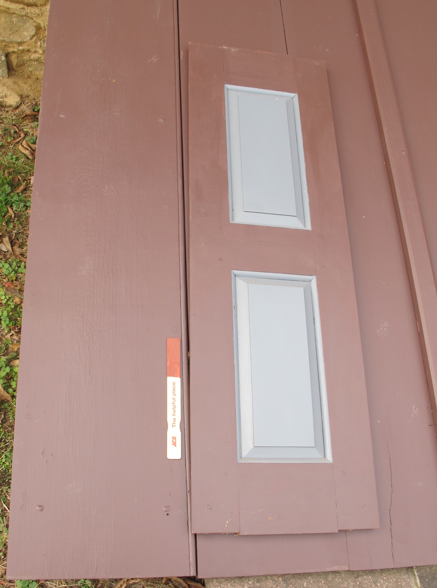
Framing, cheek sheathing, and rake boards have been installed per proposal. Doors and rest-posts will be installed soon. Paint analysis on other exterior woodwork suggests "Spanish Brown" as the appropriate finish color. Photos 7436 & 7440 show framing, sheathed cheeks with horizontal boards, and rake boards on the frame rafters.
George Douglass House:
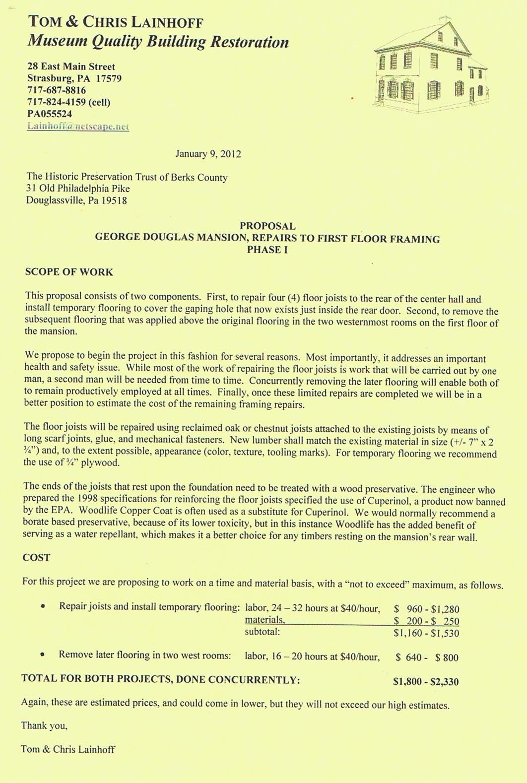
Tom & Chris Lainhoff have submitted a proposal [attached] for phase 1 of the stabilization and restoration of the George Douglass house floor framing. Photo 3553 shows the rotted joists at the door in the east eaves wall. The cost for labor and materials would fall between and is not to exceed $1800.-2330.
Board approval is requested. Funding would be provided by Shelley grants and existing balance of contributions toward GDH restoration.
Douglass, Douglass-Jenkins, and "Amity" Store Ledgers
The six bound record books discussed in the November report have been delivered to the HSBC in archival boxes provided by the Trust. The HSBC has issued an Incoming Loan Form [attached] dated 1/3/12 acknowledging receipt of the ledgers and day-books on a loan basis, renewable annually. The Trust has the privilege of removing the books for one-month periods, subject to reasonable access for researchers. The loan document is attached and will be recorded in the archives.
We should consider providing specific insurance for the ledgers and other valuable items, in conjunction with the artifact cataloguing process initiated by Trust intern Allessandro Russo and archivist Jon Hartman. Jon has catalogued the ledgers and day-books for the archives.
Morlatton Parking Lot:
The Construction Agreement with Amity Twp is in final form, ready for signatures when the License Agreement is completed and approved by both parties. We have fixed prices [subject to extras] with the site contractor, subject to Board approval. The complete project budget will be circulated to the Board when finalized.
Leslie Rebman will present the Grant Agreement for approval by the Board and return to the Greenway for signature and 90% draw-down of funds..
The final site plan and E&S Plans were submitted to the conservation District this afternoon. The approval process normally takes 2 weeks.
We have requested our insurance agent Kevin Anderson to quote liability coverage for the parking lots and the additional liability coverage to secure the indemnity requirements of the grant agreement.
Attached are sketches of the details of the log perimeter system.
Tom is working with Chazz Lyons to provide elect. to the site for drill and other power equipment.
Requested Board action:
1. Discuss and approve Lainhoff proposal on GDH floor framing.
2. Decide on cellar door rest-posts [locust from Morlatton] for KH bulkhead entry.
Consider providing a sheltering structure for the KH root cellar to preserve and exhibit it as a study-piece; discuss form and details; authorize preparation of design options.
3. Designate storage space for mission-related items, or other period items deemed worthy of retention as examples of significant architectural elements, to be removed from public and interpreted spaces.
4. Dispose of non mission-related and non-usable architectural artifacts, such as shutters, window sash [after removal of period glass?], doors, etc., in conformity with policy adopted by the Board; Jim Lewars suggested offering disposable items for sale, then for donation if there is no market.
5. Approve parking facility Construction Agreement and Grant Agreement and authorize officers to sign them and License Agreement after circulation to Directors.
The License will provide that the Trust has the rights: to participate in the construction of the parking facility on Township land in accordance with the Construction Agreement and final Plan; to reserve parking spaces [leaving a reasonable number for Trail users and the public] for meetings, tours, and other group activities and events on 100 dates per year for 25 years; to erect signs, gates, and guide-posts to secure the reservation rights; to create the "White Horse Trail" with permeable natural materials; no overnight parking except for pre-arranged encampments or other appropriate events.
Submitted by the Sites & Structures Committee.
Laurence Ward, July 2016
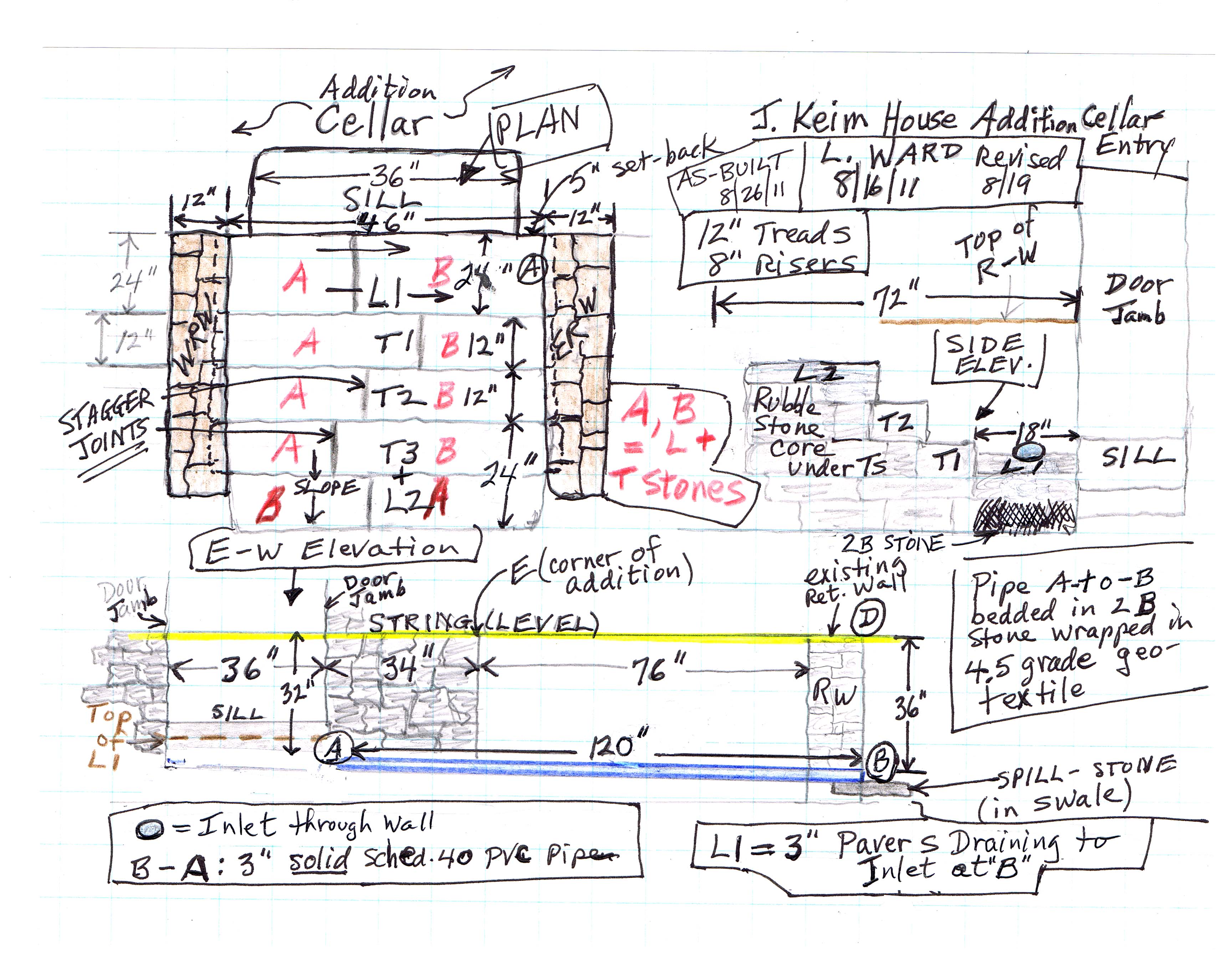
Digital images of 2 field notes drawings and a series of 8 digital photographs showing the cellar entryway constructed in summer, 2011 at the c.1800-1820 addition to the Jacob Keim House. During most of the past 90 years, the addition-cellar doorway [Image #3, photo 3676, 5/23/11] and its approach, an earthen ramp, were sheltered against direct precipitation and roof runoff by the porch built in about 1930 [see Record KR11PH3]. Removal of the porch in July, 2011 eliminated the shelter it afforded, and exposed the cellar doorway and the ramped grade-path to direct precipitation and roof runoff, as well as ground-surface "sheet" flow to the doorway, a virtual "funnel" located at the low-grade along the southern foundation walls [Image #4, photo 5310, 8/13/11]. Significant rainfall and the resulting surface-flow inundated the addition cellar between the time of removal of the porch and the installation of the retained cellar steps and pipe draining the paved lower landing of the new stair-block.
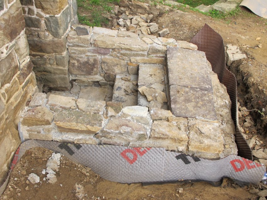
The stone stairway and retaining walls shown in the two sets of drawings and photographs in this record were designed to mitigate the ground and roof runoff into the addition cellar through this doorway. The integrated stair-wall structure consists of:
(a) a lower landing floored with flat stones ["flags"] laid in a random ["crazy"] paving pattern [Image #5, photo 5642, 8/25/11, and Image #6, #5804, 9/1/11]
(b) two intermediate steps formed by two stones ["treads"] each, with their inward faces constituting "risers" and
(c) two larger stones forming an upper landing and creating a natural riser, with treads level with the existing grade situated 24 inches above the lower landing pavement.
The tread-stones and two-stone upper landing are supported on a "rubble" stone core set in mortar, and bedded several inches into the adjacent retaining walls, producing reciprocal mechanical bond and a strongly integrated stair-block.
The walls flanking the steps will serve the usual function of retaining the soils abutting the stairwell, and will provide the additional benefit of diverting the ground runoff around the entry-way to swales conducting the flow down-grade [to the south] from the yard area south of the house and federal-era addition [Image #7, photo #5841, 9/3/11].
Roof runoff and direct precipitation into the "catch-basin" formed by the lower landing will be conducted to an absorption and discharge area by a solid 3-inch Schedule 40 PVC pipe extending at a ¼-inch per foot pitch through the backfill and two retaining walls to the lower grade 9 feet east of the cellar doorway.
The backfill around the new cellarway structure includes a bed of small stones serving as a "French" drain wrapped in a 4.5 gauge geo-textile filter fabric deployed to minimize clogging from soils above the stone drainage course. The water collected in this system will pass through the earlier retaining wall within the opening serving as the conduit for the drain pipe from the lower landing.
Tamped clay was back-filled against the building and retaining walls after insertion of a vertical sheet material forming a water barrier ["Delta-Drain"; see photo Image #8, #5650, 8/26/11] to protect foundation mortar from disintegration. Mixed soils were then filled-in on top of the clay. The area will be sodded or seeded to inhibit erosion.
The as-built stair-wall structure is shown in photos Image #9, 5834 and Image #10, #5836, 9/3/11.
DETAILED CAPTIONS
Image #3, 3676: Doorway to addition cellar prior to removal of porch and construction of retaining walls and stone steps.
#4, 5310: Excavation for cellar steps and cheek walls.
#5, 5642: Retaining walls, steps and landings substantially completed, prior to leveling ["flushing"] up east retaining wall.
#6, 5804: Both retaining walls leveled; Delta Drain membrane set in vertically against sub-grade stonework to conduct soil moisture to stone drainage course.
#7, 5841: Rough grades and drainage swales established.
#8, 5650: 3-inch stones back-filled as drainage path.
#9, 5834 and #10, 5836: Completed walls, steps and raked grades.
Laurence Ward, 2011; updated January, 2021
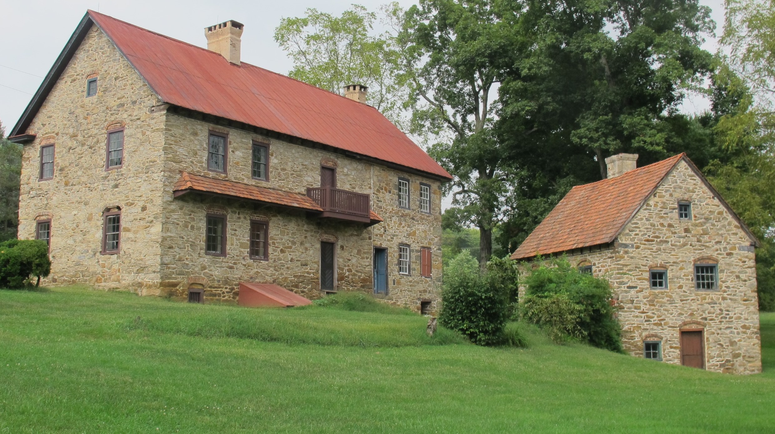
Perspective drawing of the Jacob Keim “Manor House” from the southwest, published in the copyrighted April, 1975 issue of “American Folklife, A Monthly Newspaper Devoted to the American Culture”. This image and the text excerpts are published here with the generous permission of Richard Shaner, Publisher, Managing Editor, and principal contributor to the essays and captions of "American Folklife."
In the text accompanying this rendering, Mr. Shaner observed that “A colonial balcony on the south side of the Keim Manor was altered when the home was given a huge porch which currently covers two sides of the manor. Upon investigation the staff discovered that the old porch ceiling still contained the original out riders to the colonial balcony…. Also incorporated in the porch roof line on the south side was an original out rider for the colonial pent which joined the balcony. This out rider gave…the exact measurement for the depth of the original colonial pents and an idea of their pitch.”
The perspective of this rendering suggests a symmetry in the façade that did not exist in the main elevation of the original 1753 house. The added bays to the east [right] of the door and balcony date to about 1800. The originally asymmetrical placement of the door in the east end-bay resulted in a “side-passage” alignment of the kitchen entry and second story balcony. Most of the antecedent and contemporary houses with a balcony were central-passage “Pennsylvania-Georgian” types such as “Grumblethorpe” in Germantown [Lithographic perspective view in "Quaint Old Germantown," Plate VIII], the Peter Wentz house in Worcester Township and Muhlenberg Houses in Trappe (both in Montgomery County), and “Bellaire” in Philadelphia [see "Worldly Goods," p. 84, and Kornwolf, Vol. two, p. 1223]. All houses cited except Wentz currently display a balcony surround of neo-classical turned balusters and molded handrail; Wentz’ rendering is scroll-sawn “splat” form, apparently based on the choir-railing at Trappe Lutheran Church.
The Keims were wood turners by trade, producing lathe-turned spindles and possibly balusters in the nearby and contemporaneous workshop structure southeeast of the house. Nonetheless, the vernacular Georgian houses cited above, with centrally-aligned balconies with turned balusters, would not seem to provide compelling templates for re-producing a balcony for the decidedly Germanic, asymmetric, and uncoursed masonry façade of the Keim house. Currently under consideration is a plain or edge-beaded board form, as suggested by a board railing on the second floor of the house.
The porch on the west gable wall and south eaves wall mentioned in this article was almost certainly added in the 1930s, based on photographs and analysis in record KR11PH3 [see photos and accompanying text in archive records KHPH8--1002.01.027, KHPH9--1002.01.044 & KHPH13--1002.01.057], and is without historical precedent as to form or appropriate scale with respect to the earliest bays of the house. The intermediate porch [see KHPH9--1002.01.044]--probably constructed circa mid-nineteenth century after disintegration or removal of the original pent roof--did not wrap around the corner or extend across the gable wall. Neither porch roof tucks closely under the projecting stone flashing course, which therefore does not effectively protect the joint between the porch roof and the masonry wall from moisture infiltration, as it did for the original pent roof [see pent on road-front (north) eaves wall, which provides a virtual template for the proposed pent roof on the south eaves wall].
Other period or recreated early details rendered in this drawing include: central chimney on original bays; gable-end chimney on early addition [right bays]; pent eaves on west gable; pent roof on south eaves wall; second storey “colonial balcony”; brick oculus vent in west gable apex; brick relieving arches; western corner of original pent roof on north eaves wall; stone-arched cellar entry; northwest corner of 18th-century ancillary building [right edge of drawing].
See KHTX2--1002.01.021 for the full text printed below this drawing reproduced on page 12 of the issue cited.
Archive record KHTX8--1002.01.048 is the text accompanying a conceptual northwest perspective drawing of the original manor house by Gerald O’Brian, rendered without the early eastern addition, and published on page 12 of the April, 1974 issue of Richard Shaner’s “American Folklife.”
Laurence Ward, Updated 2020
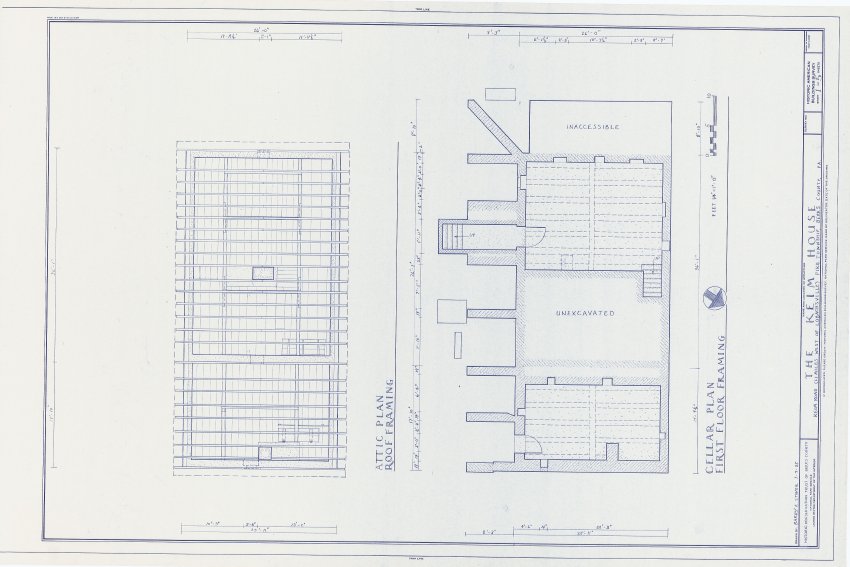
These drawings from the 1980s show the Keim House prior to its restoration, which included removal of the 1930s porch [see record KR11PH3], reconstruction of stone stairwell to cellar [KR11PH1], reconstruction of the original 1753 pent roof [KHPH19 and KHPH13], and restoration of the first-period 2d floor exterior balcony and plastered cove cornice applied to original coved brackets radially cut into attic joist-ends.
Larry Ward
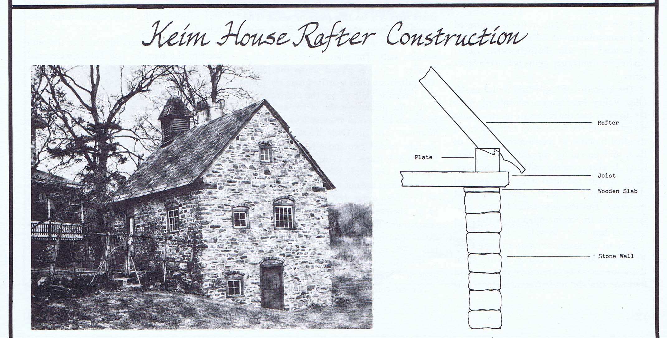
Photo and sketch of the Keim multi-purpose ancillary structure [formerly considered a “Cabin”] from an article written by James A. Lewars, entitled "Pennsylvania German Kicked Roofs," published on page 12 in the Winter, 1981 issue of the ‘Historical Review of Berks County." Image and text from the original article focus on the techniques used in the construction of the building's roof rafters and their support framing.
Notable text passages included from the article:
"The Keim House, a one-and-a-half story stone house in Pike Township, is one of the earliest houses in the Oley region. It is a straight roof center-chimney house and exhibits almost the identical framing method found in the Bertolet outbuilding."
"The Keim House makes use of the attic floor joists as supports for the [rafter] plate…."
"The stone walls of the Keim House are topped with a wooden slab. The attic floor joists then rest on this piece of wood{1}.... The spaces between the joists are filled with stone, the stone being laid directly on the wooden slab. The plate, in the form of a wooden beam, is placed across the joists. The rafters are then mortised over the plate{2} and form the support for the overhang."
ARCHIVE EDITOR'S FOOTNOTES
{1} Because of this function of providing a level bearing plane for the joists, sometimes called a “joist plate”, "leveling plate", or "leveling board."
{2} Based on this support role, sometimes called a "rafter plate," or, more generically in modern terminology, a "wall plate."
Record edited and updated by Laurence Ward, February, 2021
The10 joists {1} that have supported the 2d floor of the 1716 Mouns Jones house for approximately the past half-century are not original to the building and are undersized, averaging 6" or less in vertical dimension. They were provided from a dismantled log house in northwestern Berks County in the late 1960s.
The earlier joists, in place from the period or periods in which they were installed through the mid-20th century, had collapsed by 1957, when the roof framing, floor boards, and partitions from upper floors fell, partially destroying the attic and 2d floor boards and their supporting joists. This structurally catastrophic event, probably caused by roof neglect and the resulting rot and deterioration of the roof framing, left some joists in place but severely damaged; others were driven to the first floor by falling materials. Some joists, from both the 2d floor and the attic floor set, were shorn from their bearing "pockets" in one wall, but were still bedded in the opposite wall and resting diagonally on the floor or on fallen debris [photo #73, 60s slides]. The 1957 HABS report [Image #2, 10/22/17] noted silt and debris on the first floor, but mistakenly reported that this material had filled-in a cellar. The archaeological evidence excavated recently indicates that the building never had a cellar. Consistent with this finding, Theresa Beard, the Trust's lead representative on the Mouns Jones House project in the 1960s and its President in the early years, recorded her observations that "The house had no cellar, only stone piers holding the rotted floor joist." Probes angled under the foundation base, about 12 inches below ambient grade, confirm Mrs. Beard's statement. [photo #4, 11/17/17]. Interior archaeology will be conducted to verify and locate the stone piers aligned across the short axis of the house to support and the attic floor set, were shorn from their bearing "pockets" in one wall, but were still bedded in the opposite wall and resting diagonally on the floor or on fallen debris [photo #73, 60s slides]. The 1957 HABS report [Image #2, 10/22/17] noted silt and debris on the first floor, but mistakenly reported that this material had filled-in a cellar. The archaeological evidence excavated recently indicates that the building never had a cellar. Consistent with this finding, Theresa Beard, the Trust's lead representative on the Mouns Jones House project in the 1960s and its President in the early years, recorded her observations that "The house had no cellar, only stone piers holding the rotted floor joist." Probes angled under the foundation base, about 12 inches below ambient grade, confirm Mrs. Beard's statement. [photo #4, 11/17/17]. Interior archaeology will be conducted to verify and locate the stone piers aligned across the short axis of the house to support the first floor joists. {1} A species of beam in tension between bearing beds and, with the other joists at the 2d floor level, supporting an aggregate "dead" load consisting of, in the Jones house, flooring, partitions, and any other architectural fabric borne by the integrated structural diaphragm forming the floor. The incremental "live" load imposed on a floor by people and moveable objects must also be considered in the calculation of the total load to be supported by the floor joists. The vertical dimension, critical to the bearing capacity of a joist, is squared in calculating the structural value of a beam. Thus,an 8 vertical-inch joist is 77% stronger than a 6 inch joist, even though only 33% greater in vertical dimension.
All of the current [March, 2018] 2d floor joists [photo#3, 4/6/17], showing the joists after removal of the floor-boards installed in the late 1960s] must be replaced because they are functionally undersized, "checked" (longitudinally split to varying depths into the timber), and deflected from the critical horizontal alignment necessary for structural stability. All are less than the 8 inch vertical dimension of the original joists as noted on the 1957 HABS drawing. Further, some of the joist-ends bedded in the eaves walls are rotted or have been degraded by infestation to an unacceptable extent. The replacement joists will be bedded on leveling plates that also serve as lintels over the window and door openings [photo#15, 4/5/17]. The leveling plate [ functionally, "joist plate"] in the southwestern (river-facing) wall is a recent lapped two-timber replacement; the white oak 18-foot long bearing plank embedded in the northeastern wall is original and over 300 years in place, undoubtedly one of the longest-functioning pieces of framing lumber in the region.
The method of treating the lower arrises{2} of the replacement joists [5" x 8" white oak, as observed by the HABS surveyor] involves various options based on traditional historical moulding profiles and any specific evidence available regarding the original joist detail in the 1716 house. The conventional range of choices for early 18th century moulding craftsmanship includes the following:
1. Hewn or roughly planed vertical faces and soffits, with no chamfers, beads, channels, or other mouldings on the intersecting surfaces [photo#73, 10/12/17, a circa 1964 photo of joists supporting the 2d floor of the Mouns Jones house in the parlor comprising the southern and part of the central section of the first floor hall-parlor interior space];
2. Hewn faces with chamfered corners, as in the 1753 Keim House 15 miles to the North [photo#26, 6/9/17], and the 1767 DeTurk ancillary house [photo#........], in which the chamfers return to the arrises by a sloped "lamb's-tongue" chamfer-stop transition.
3. Roughly-planed faces with untreated corners [Amity Store attic joists photo #78, 1/11/18];
4. Hand-planed surfaces, sometimes smoothed to a uniform plane, with edge- [or "face"-] beaded corners and "quirked" channels above the semi-cylindrical bead moulded into the vertical surfaces of the joist along the arris [photos#17, 11/13/17, 60s slides, and #2 and #47, 11/15/17, cropped segments of #17], but no channel in the joist's lower surface; photo #54 of the 1960s slides also suggests the possibility of a bead on the fallen joist running diagonally across the image.
5. Hand-planed surfaces with rounded ["eased"] arrises and grooves only on the joist's lower (horizontal) surface [the "soffit"] between arrises [photo#84, 1/11/18, the joists supporting the 2d floor of the late-Federal Amity Store addition to the George Douglass House], ;
6. hand-planed surfaces with full-corner beads, grooved ["quirked"] on both the intersecting vertical faces and the soffit, [photo#18, 11/13/17];
7. Hand-planed faces with corner beads and "fileted" quirks, which return to the vertical planes with a small right-angle rabbet cut into the timber adjacent to the quirked channels on both faces [photo "DTH corner bead", 12/28/17 is a sketch of the corner bead treatment on the window frames of the 1757 DeTurk House 10 miles north of the Mouns Jones House];
{2} In this instance, the perpendicular intersections of the horizontal and vertical planes of the joist, most commonly called the "corner" of the timber.
The critical question is: Which of the above corner treatments of the replacement joists is most appropriate and historically authentic based on the inferred original joists in the Mouns Jones House? There is no unequivocal evidence on this determination, but the 1960s project photos and the HABS "edge-bead" observational note are consistent with applying "edge"- or "face"- beads to all 10 joists above the original "hall" and "parlor" segments of the first floor. This analysis requires a determination, to the extent possible, of what is discernible as a three-dimensional projection of a detail visible in a two-dimensions in a photographic image of imperfect resolution.
A 1964-1965 colored photographic slide in the Trust's collection [photo #47, 10/12/17] shows a segment of the three 2d floor joists closest to the gable-end fireplace in the "hall" [northern, "kitchen"] section of the 1716 Mouns Jones house. None of these joists (numbered J1, the joist closest to the fireplace seen as the dark timber along the bottom of photo 47; J2; and J3) survives or was measured or otherwise documented except for the slides and the HABS note quoted below. No ascertainable date of installation of any of the early-period joists shown in the attached images has been documented. Close examination of photos #17, 2, and 47 clearly indicates a sunlight angle from above the 2d floor level, either through a 2d floor window or between shingle-less rafters and joists missing floor boards. The direct sunlight from above has cast three "sun-panes" on the southern face of J2. This sun-angle is consistent with the light and shadow on the apparent "beads" on the lower corners of the eastern runs of J2 and J3 (to the right in photo 17) below the narrow dark band, which would be in the exact relative position and alignment of a "quirked" groove above the bead. Just below the dark groove in deep shadow, is a slightly wider and lighter horizontal band of woodgrain consistent with the upper quadrant of a cylindrical profile of a bead lit by angled sunlight from above. Below this lighter segment is a somewhat darker band, which is reasonably interpreted as the lower quadrant of the bead, in shadow. This profile, light pattern, dimensional proportions, and parallel positioning of the three bands of differing light-reflection and absorption (shadow) express with reasonable certainty a short-radius bead with a "quirked" groove above each cylindrical-segment moulding [photos MJH J 1,2,3 and #9 attached] in runs along the arrises of joists J2 and J3. This interpretation is convincingly reinforced by the HABS "edge-bead" observation noted above. Photo #73, 10/12/17 shows hewn surfaces with unmodified arrises on some 2d floor joists in the Mouns Jones House. This circumstance is inconclusive as to the early treatment of the 2d floor joists because the dates of installation of the hewn joists are unknown. They quite possibly were installed as part of a reconstruction project in the 19th century after a partial collapse of masonry segments of the western and southern walls of the house{3}. These hewn joists were in the "parlor" section as it existed in the original floor plan or after its 19th century expansion into the southern portion of the early hall/kitchen space. Some of the apparently hewn joists in the "parlor" section of the first floor might plausibly indicate a different level of joist finishing in the two rooms composing the hall-parlor floor plan and a different perspective from the traditional hierarchal ranking of the two spaces {4}.
{3} Large ranges of original red sandstone "units" have been replaced by gray-tone limestone in the reconstructed intersecting bays of the two repaired exterior walls.
{4} In the traditional hierarchy of refinement in Anglo-Pennsylvania hall-parlor dwellings, the "parlor" would receive more skillfully decorated treatment. However, there is no evidence that Mouns Jones and his family used the two rooms on their first floor within their traditional
Anglo-American allocations of function between the "hall" and the "parlor"; or that the "parlor" space in their "backcountry" home was used for more public or mercantile, and thus presumably more ostentatious, purposes; or whether the Parlor was a private family space partitioned from the "hall" and not used for treating with guests or associates in the Indian Trade or otherwise intended for public display, and thus less formally decorated or aesthetically refined.
Although deterioration, checking, delamination, and possibly modification, obscure or deform the early treatment and detail of the joists, they also imply an early date for these joists. These deforming factors obscure much of the detail of face condition as well as confuse original arris treatment. However, if the "beads" perceived in the expected parallel alignment in the visible arrises of the two contiguous joists [J2 and J3] are original treatment, it may be reasonably inferred that the joists were initially moulded in this manner along their full lengths. There is no rational explanation for beading only a portion of an arris which is visible along its full extent. However, there are plausible inferences explaining the absence of unambiguous "beads" on deteriorated or modified segments of the joist arrises, most obviously the inference that what is seen is the deteriorated or modified arris and not the joiner's original moulded finishes.
The photographic evidence does not provide a view of the underside ["soffit"] of any of the early joists, and the HABS "edge" bead notation does not support a conclusion that the joists' horizontal soffits were beaded or grooved. We conclude that there is no evidence of a beaded arc or quirked channel on the underside of the 2d floor joists.
Edge-beads will therefore be specified for the original parlor-space joists as well as those in the hall/kitchen, consistently with traditional room hierarchy in the early period. This interpretation is consistent with the HABS "edge-bead"{5} note on the 1957 drawing [attached], which suggests grooves only on the vertical faces above the bead, but none on the soffit of the joist. The HABS note also specify 5" x 8" joist dimensions, which provide an approximate scale for sizing the bead and quirk combined at 5/8".
{5} also called a "face-bead" in a draft HABS survey report on the 2/17/67 DeTurk house [archive record DTHTX…….],Part II, C, 6, a, which distinguishes the face bead there from a "corner" bead.
Laurence F. Ward, March 2018
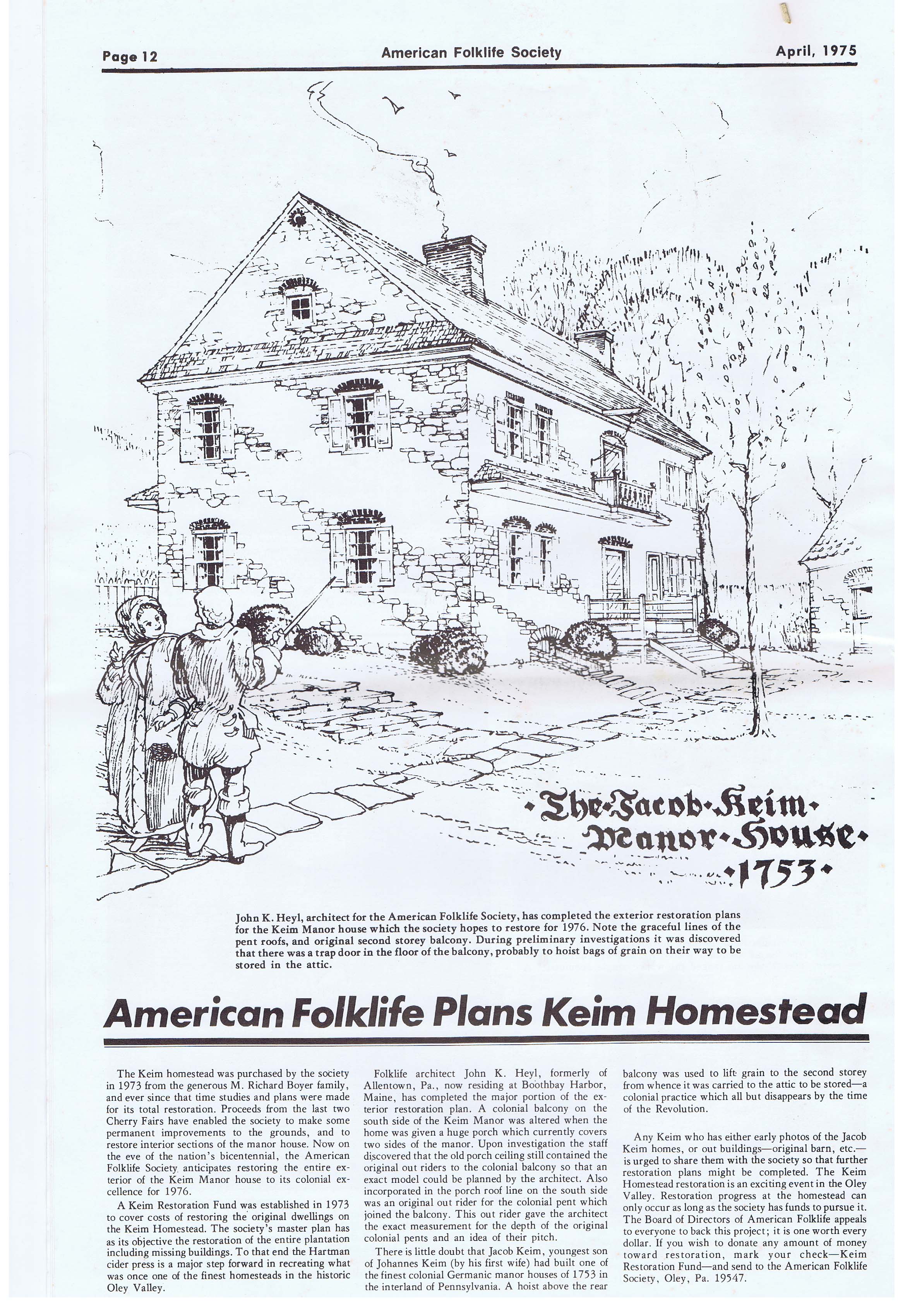
Full-page article with illustration from page 12 the April 1975 issue of "American Folklife," newsletter of the American Folklife Society.
Article briefly outlines restoration plans for the Jacob Keim Farmstead, focusing on balcony, porch, and Hartman cider press. Also requests Keim descendants to share property photos as well as an appeal for funding.
At the time this article was written Keim Farmstead was owned by American Folklife Society.
Also see record KHDWG1--1002.01.070 for further information regarding the drawing that appears as part of this article.
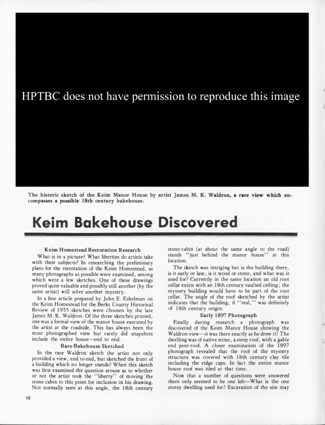
Two-page article appearing on pages 10-11 in the Winter 1974 issue of "American Folklife,"journal of the American Folklife Society. Article on Keim Farmstead discusses the depiction in a drawing of a structure (bakehouse) not present on the site in 1974. The vaulted “root” cellar remains, and will be exhibited under a roofed shelter.
Article also discusses how the presumed bakehouse was discovered in an 1897 photograph of the property. [See archive record KHPH13--1002.01.057 which reproduces the 1897 photograph from a halftone.] Both the drawing that initiated the controversy and the discovered 1897 photograph are reproduced in the 1974 article.
Image is of first page only. See additional image or MULTIMEDIA LINKS for second page text.
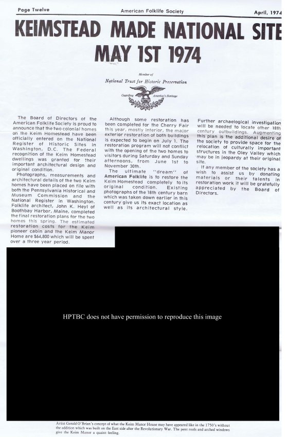
One-page article with conceptual perspective drawing (by Gerald O'Brian) from page 12 of April 1974 (Volume II, No. 7) issue of "American Folklife," newspaper of the American Folklife Society.
Article briefly discusses the appointment of the farmstead's two colonial homes [Keim Cabin & Keim House] to the National Register of Historic Places as well as restoration plans for the site and public access to the buildings.
At the time this article was written Keim Farmstead was owned by American Folklife Society.
Since 1974, considerable research has been done on the Keim farmstead structures by Philip Pendleton [primarily in his book “Oley Valley Heritage, The Colonial Years” and notably in his successful application for the designation of the 1753 Keim House and the “Ancillary” jointly as a National Historic Landmark [See summary in record KHTX13 in this archive]. New information and analysis have determined that the 3-level building formerly called the “Keim cabin” [or, even more speculatively, without documentation, the “Keim settler’s cabin”] was in the early period a multi-function building “ancillary” to the farmstead and the 1753 farmhouse, and housed the wood-turning craft engaged in by several generations of the Keim family. The “Ancillary” is now believed to be contemporary with the 1750s farmhouse rather than from an earlier generation of Keim settlers.
Updated August, 2020, Laurence Ward
November 2017 Sites & Structures Newsletter Update:
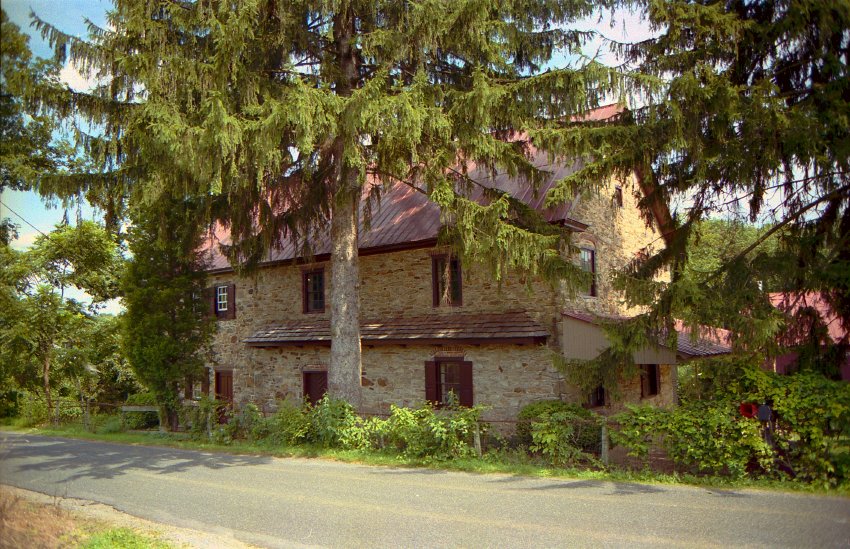
Keim House: The Trust’s five-year campaign to restore the Keim House to its 1753 architectural composition and appearance was completed in November, 2016. Within a month, National Historic Landmark status [see plaque photo] was awarded to the house and wood turner’s shop, a rare recognition celebrated at the Trust’s November 4 th, 2017 Gala Dinner. A month earlier, Preservation Pennsylvania had conferred its statewide Preservation Stewardship award on the Keim project, which re-created the pent roof, balcony, and plastered cove cornice, and restored the stone steps and stone-arched entryway to the half-cellar under the first-floor Stube and Kammer.
Mouns Jones House: Photographs taken a few years after the roof had collapsed in the late 1950s indicate that the ten exposed joists supporting the 2d floor were "edge-beaded", a refinement which will be recreated in detailing this important architectural element. "Edge-beads" had been specifically noted on a 1957 drawing by the Historic American Building Survey, now lodged in the Library of Congress. None of the early joists survive, thus the photographic evidence and HABS note, entirely consistent with one another, are crucial in determining the authentic treatment to be applied to the replacement "floor-beams". X-ray analysis of the primary elements of the early mortar used in the foundation and walls of Mouns Jones’s house has determined the precise chemical composition of the early lime binder. This "dolomitic" limestone type is nearly identical to geologic formations close to the northern range of the Mouns Jones tract nearly four miles north of his surviving stone house. An American source has been located for chemically and functionally equivalent lime-mortar that will be used in the masonry re-building campaign in 2018.
George Douglass House: With the generous aid of a Pennsylvania Keystone Grant, matched by funds from the Donald & Esther Shelley Foundation, the Trust will undertake a major restoration program in 2018. The primary objectives will be completion and stabilization of all flooring in the building, interior plasterwork, and re-plastering of the exterior "encircling" [yes, we know it’s rectangular!] coved cornice, and complete restoration of the "best parlor" and its elegant and surprisingly colorful paneled and moulded woodwork. The completed project will accommodate the re-dedication of the structure as the "Shelley-Pendleton Education and Exhibit Center" as resolved by the Trust’s Board earlier this year.
Morlatton Village Pathways: In 2018, stone-bordered and stabilized-soil paths will be installed to provide access to all building in the Village and to the Thun Trail. The pathways plan has been approved by the Trust’s Board and has been submitted to Amity Township for its review. The pathway surface material, suitable for pedestrians, cyclists, and wheelchair-borne visitors, will be acquired from the same local quarry that supplied the durable top-dressing on the Village parking areas. The border-stones leading to Trust buiildings, which will provide containment and weed-buffering for the pathways, have been gathered from the Village grounds.
See record HPTSSR46 for additional discussion of the above issues.
Larry Ward, July, 2022
Series of 19 images showing perspective views of the Keim House and other dwellings, detail views depicting evidence of an early plastered cove cornice on the Keim house, and other related photos, including images of houses built during the same quarter-century period as the Keim house and earlier English antecedents displaying plastered cove cornices.
Image #1, an early 20th century view, appears to show deteriorated remnants of a coved plaster{a} cornice under the second story eaves of the 1753 house [left of roof extension above the second story balcony], and on the c. 1805 addition [right of roof extension]. Images #2, 3, and 4 are colored digital images provided by restoration craftsmen and consultants Tom and Chris Lainhoff, showing coved oak joist-ends{b} with nail holes for lath, confirming that an early plastered cove cornice existed, most probably from the first period of the 1753 house. This conclusion is reinforced by the un-coursed "rubble" masonry walling behind the cornice [Images #3, #4, & #5]. Such coarse stonework would not be seen behind the plaster and lath of the cornice and is therefore not masoned as methodically as the visible wall ranges of the house. As a comparison and contrast of masonry methods on the same building, the wall ranges behind each Keim house "pent" were as carefully laid-up as all other exposed ranges of the structure because the pent roofs were not ceiled {c}.
{a} In modern usage, "plaster" ("plaister" in early British terminology), is sometimes confined to interior finishes, and "stucco" is limited to lime-based rendering applied directly to exterior wall surfaces. Early plaster was extruded ["keyed"] between wooden lath, originally riven [sometimes "hewn"], and later sawn, for anchorage.
Some scholars consider the interior-"plaster"/exterior-"stucco" distinction to be arbitrary and historically unwarranted [see Curl, A Dictionary of Architecture, Oxford U. Press (1999), page 645]. Other respected authorities seem to prefer "plaster" in describing interior renderings, invoking the earlier term "roughcast" for coarsely aggregated exterior coatings [e.g., Lounsbury, Carl, Editor, An Illustrated Glossary of Early Southern Architecture and Landscape, page 279]. In the context of Mid-Atlantic vernacular building forms and practices, the highly regarded authors noted that "Stucco…[was] sometimes applied to interior walls…(though more commonly to describe an exterior finish)" [Lanier & Herman, Everyday Architecture of the Mid-Atlantic…Buildings and Landscapes, Johns Hopkins University Press (1997), p. 113]. The legendary Renaissance stone mason and architect Andrea Palladio invoked the term "stucco" to describe the decorative plaster coating applied to interior niches in his villas.
Other scholarly textual sources uniformly describe cornices as "plastered" when specifying the material applied to exterior coved eaves transitions (e.g., Richie, Kornwolf, Murtagh, Schiffer, Tinkcom & Simon). It is clear that there is no consensus among the academic community endorsing the use of the terms "plaster" and "stucco" based merely on interior or exterior applications.
{b} Compare the lath-nailing system of the George Douglass house, where concave brackets are suspended from the sides of the cantilevered attic-floor joists [see Image #6] projecting beyond the top of the rubble segment of the wall, and are footed on the projecting upper surface of the squared and dressed sandstone blocks forming the top course of the "ashlar" façade. [Image #6, photo "GD cove brackets 2", 8/23/13]. Images #7 & #8, Photos 2950 and 2951, 7/12/13 show surviving plaster fragments of the early cove cornice on the Douglass house [Images #9 & #17]. The convex view in Image #7 clearly shows the thin plaster "keys" which extruded through the narrow gaps between lath, securing the finished cornice in the coved profile established by the brackets.
{c} earlier: "sealed", typically with board sheathing.
The nail holes in the coved joist-ends of the c. 1805 addition to the 1753 Keim house are spaced differently from those on the early house, indicating that the two cornices, though approximately conformed in dimension and cove radius, were applied in different periods, probably separated chronologically by the approximately half century between the 1753 house and the Federal-era addition project. Therefore, the two cornice segments, though jointed in some manner when the addition's cornice was plastered, never formed a monolithic concave band across the contiguous eaves of the two house-blocks. Unless the cornices were re-plastered contemporaneously in a later period [of which there is no evidence], they were never unified in a single plastering campaign. The current [2013] restoration program relates only to the 1753 house, including its cornice. The coved plaster cornice on the c. 1805-10 addition will be considered for a future restoration campaign.
One of the earliest cove cornices in the Philadelphia region appeared on the three bay pre-Georgian Anglo-Pennsylvania Chalkley [Letitia Street] house (c. 1703-1715; see Tatum, Penn's Great Town, plate 6, and Fig. 2 in Smith, Two centuries of Philadelphia Architecture, 1700-1900, offprint, pp. 291-303, from Transactions of the American Philosophical Society, New Series, vol. 43, Part 1, March, 1953, which describes the cornice as constructed of wood), built in central Philadelphia and since 1883 situated on its re-located site in Fairmount Park. Smith's "Two Centuries" paper notes in footnote 6, p. 290, "three houses with pent roof and cove cornice"…[on] Cuthbert Street in Philadelphia.
Another early Philadelphia house with a cove cornice, "that would become so typical of the Delaware Valley" [Kornwolf, Architecture and Town Planning in Colonial North America, Vol. Two, p. 1223], is the surviving two story, five-bay "Bellaire", c. 1714-1729, an early Georgian plan-form with English Baroque decorative elements, and built for the prominent Quaker Mayor of Philadelphia and Provincial Treasurer, Samuel Preston [see Worldly Goods, p. 84, Phila. Museum of Art, 1999].
The "High Street" [2d and Market] "Greater" Meeting House, built c. 1695 and re-built in 1755, and the old Court House/Town Hall across the street from it, also featured full-perimeter ["encircling"] coved and plastered eaves cornices in their early periods [see Tatum, op cit., plate 8].
A five-bay brick house, the 1730 William Miller house in Avondale, Chester County, PA, prominently boasts another "encircling" plastered cove cornice, added at the attic floor level when the third story was erected in 1771 [Schiffer, Survey of Chester County, Pennsylvania, Architecture, 17th, 18th and 19th Centuries, page 61, Image # 19, photo miller cove cornice]. It is not clear whether a cove cornice appeared on the first-period house at the original 2d story eaves level.
Another four-range cove cornice, restored in 1950, appears on Wright's Ferry Mansion, Columbia, Lancaster County, PA, built in 1738 with roughly coursed limestone "rubble" and hybridized by some Germanic details for the Quaker "Renaissance woman" Susannah Wright.
Yet another Quaker structure with a most imposing surrounding cornice, described as a "concave, plastered support," above roughly coursed rubble walls and segmental brick "relieving" arches, is the 1768-1769 Buckingham Friends Meeting House in Bucks County, PA [see photo and caption at pp. 64-65 of Stone Houses… Bucks County and Brandywine Valley by Richie, Milner, and Huber (2005)].
It seems reasonable to infer from the early Philadelphia-area examples cited, (and some in West Jersey) that immigrant plasterers from England, who probably received training and experience in the post-fire English Baroque tradition{d}, would have been familiar with and probably influenced by 16th and 17th century specimens of prominent plastered coved cornices in their homeland. Such traditions would have been preserved and transmitted within the British building trades within the prevailing and ancient master-journeyman-apprentice system under the auspices of craft Guilds devoted to the "art and mystery" [craft methods and trade secrets] of each artisan group. Plastered cove cornices, some on half-timbered town-houses with curvilinear plastered eaves-panels, appear on substantial houses in 16th and 17th century England. Examples would include half-timbered 16th century structures Congleton, and Moreton Old Hall, both in Chesire, and a dormered three and a half story Town House in Bisley Street, Painswick, and the symmetrical three-bay pre-Georgian house in Lechlade, also in Gloucestershire. These antecedents, graciously brought to the Trust's attention through the scholarship of Joe Kindig III of York County, would have provided an abundance of prototypes for emigrant plasterers re-settling in Penn's distant colony, and their protégés. Examples from the late half-timber period appear in photographs published in British Bouquet, An Epicurean Tour of Britain (1963) by noted architectural photographer and etcher Samuel Chamberlain [images #10, 11, and 12].
{d} This tradition included numerous variants and applications, in architecture and decorative arts, of the "C-scroll" motif and the Renaissance (originally Roman) versions of the "cavetto" moulding profile.
The National Register application on behalf of the c. 1698-1700 Reynolds house in Bristol, RI describes "an original plaster cove cornice" as "a rare survivor following late seventeenth century English precedents". Several plastered cove cornices in New England and the southern tier of the mid-Atlantic states are recorded in HABS and National Register records.
An impressive concentration of houses with coved lath-and-plaster cornices, some with shed-form roofs ["pent eaves"] across the gable walls and most constructed in the 1740s, appeared in German Township, later the Germantown wards of northern Philadelphia but then an independent community established by a Penn grant 10 miles north of Philadelphia in the late 17th century. Notable among these are the earlier (of two) Gorgas ("Monastery") house, 1746-47 [see image #13, photo #gorgas], and the earlier (of two) Daniel Pastorius house [1748, image #14, photo #3402], later known as the Green Tree Inn. Other mid-18th-century stone houses in Germantown with plastered cove cornices include the early 18th-century De La Plaine house [demolished 1885], which was gambrel-roofed and dormered (wounded Civil War veteran John Richard's lithographic Plate X); and the (Van Lauchet) Weygandt house (Richard's Plate XXX , also gambrel-roofed, with an asymmetric street façade. Plate XLVI also suggests a coved cornice on the dormered section of the house on Thorp's Lane, near the site of Weber's and Thorp's Mill. Richard's detailed drawings were published as lithographic reproductions by the Pennsylvania German Society in Vol. XXIII of its "Proceedings", Lancaster (1915), in the essay and plate collection called "Quaint Old Germantown."
The design currents and craft proficiencies producing the coved plaster cornices in the Philadelphia region in the earliest decades of the 18th century reached Germantown by 1740, and appeared in more remote northerly settlements by the middle of the 18th century, as exemplified by the cornices at Pottsgrove [1752], Keim [1753], Eshelman [Lancaster County, 1759], Abraham Landis [Lancaster County, 1763], and George Douglass [Amity Township, Berks County, 1765].
The most prominent "backcountry" house with plastered cove-profile cornices (and an English Baroque-influence re-constructed door-hood) is John Potts' "Pottsgrove" mansion [image #15, photo #265, 9/11/12], built a year or two before the Jacob Keim house, and about 12 years prior to the 1765 George Douglass house, which displays a cornice quite probably influenced by Pottsgrove, though in a more attenuated and vernacular interpretation of this and other design details. The Pottsgrove cornice is plastered on lath nailed to coved brackets scribed and "sistered" to the coved ends of the attic floor joists projected through the top courses of the walls. This system and its lath nailing pattern for the early plaster cornice, differing from the coved joists at the Keim house and the suspended brackets at the George Douglass house, can be viewed at Pottsgrove via a strategically placed mirror through a window in a second floor chamber, as the brackets and a coved plaster segment are now sheltered by the "ell" addition constructed c. 1820 and butted against the original 1752 house.
This group of houses--Pottsgrove, Douglass, and the earlier Germantown structures--all feature coved cornices framed by crown and bed mouldings above a coursed and dressed "Georgian" façade. The Keim house departs from this essentially Pennsylvania-Georgian design approach, lacking the evenly coursed ashlar block-work and central passage façade-symmetry of most of the other houses cited. The 1753 Keim house also apparently omitted a traditionally moulded "crown" piece forming the outer (and upper) termination of the plaster cove. The restored top trim board will be beaded and finished with a chamfered "drip-edge."
A slightly later (c.1768) pre-Revolution structure with several design details in common with the Keim house is the Bethlehem Widow's house depicted as plate 45 in Murtagh, Moravian Architecture and Town Planning, p. 87, and Brumbaugh, Colonial Architecture of the Pennsylvania Germans, plates 76 and 79 [captioned "Moravian Seminary"]. Although the Widow's House is laid-up in courses, is symmetrical on its principal elevation, and is dormered, both it and the Keim house (as well as the Buckingham Meeting House cited above) "relieve" the rectilinear geometry of their fenestration openings with segmental brick arches, and refine their eaves transitions with coved plaster cornices arcing between bed- and crown-mouldings.
The 1753 Keim house is undoubtedly one of the few random rubble structures in the region (perhaps a unique example) with a three-room Germanic floor plan, asymmetric eaves-wall fenestration, a coved plaster eaves cornice, a stone-arched cellar doorway, and a cantilevered balcony [to be reconstructed] above the end-bay ["side-passage"] doorway.
Two Lancaster County Germanic-Georgian houses with mixed characteristics and "encircling" coved plaster eaves cornices are:
A. the 1759 house in Conestoga Township, Lancaster County, PA constructed for Mennonites Benedict and Anna (Stehman) Eshelman [cfr. photo and floor plan in Falk, Architecture and Artifacts of the Pennsylvania Germans (2008), pp. 144-145]. Unlike the Keim House's emblematic three-chamber stove room ["stube"] plan, the Eshelman house includes a slightly off-center walled passage and rear stair-hall, and four rooms on the first floor, the larger pair (kitchen and stove-room) to the left of the hallway. The Eshelman façade is laid up in coursed and roughly dressed block-work and a full perimeter rubble course between first and second story windows, indicating that an early ceiled pent roof had been removed, an inference further affirmed by a projecting flashing course and outlooker remnants, apparently truncated when the pent was removed; and
B. The Abraham Landis house in East Lampeter Township, c. 1763 [Lestz, Lancaster County Architecture, 1700-1850, p. 54, photo].
Other Keim House Details include: 19th-century roofed porch [Image #1], replaced by the "L" form two range porch in the 1930s; second floor balcony [to be re-constructed in 2013-14], framed onto cantilevered "outlookers"; flashing ("drip") course for earlier pent roof (removed, presumably to make way for the porch roof shown in this record).
Note the absence of porch or evidence for porch on west gable wall; the L-form 20th-century porch succeeding this one is depicted in record KPH4--1002.01.009. A history of this 19th century porch and its 1930s successor, removed in 2011, and related photographs and other images appears in archive record KR11PH3--1002.01.092.
The vertical separation between the "flashing" course (which sheltered the joint between the original pent roof and the eaves wall) and the top of the porch roof shingles in these "vintage" photos appears to have been approximately 12-14 inches. With this separation, the flashing course did little to prevent precipitation from penetrating the joint between the pent roof and eaves wall, gradually and inevitably eroding or rotting the rafters and lathing of the porch roof. Signs of such decay were evident on removal of the early 20th century porch rafters and other framing members.
Laurence Ward, 2011; updated February, 2021
Digital image of 2 plan drawings showing the proposed driveway ramp at the Jacob Keim House.
Image #1 shows the plan for the driveway apron itself; the areas outlined in green indicate the industrial-grade “fiberglas”
grating providing the rigid ramp and traction from its grid pattern of bars and open cells, which also facilitated positive drainage.
Image #2 illustrates installation of the driveway bed, plan view and side-view section sketch, and the base-system and anchorage design of the ramp’s components.
Series of 50 digital photographs depicting the removal of the c. 1930s porch from the Keim House {q}.
1. {q} Image #47 is a panoramic view of the Keim farmstead, a c. 1930, photo taken by Amandus D. Moyer, and is used with the generous permission of the photographer's granddaughter Susan Harvin. Note the absence of a porch on the west gable wall.
The two earliest Keim buildings, the 1753 farmhouse and its "ancillary" structure, and the Federal-era addition to the 1753 house formed an organic and architecturally distinguished farmstead which prospered during Keim family occupancy and administration for nearly sixteen decades. The surviving structures remain in remarkably well-preserved and substantially undisturbed condition, never having been substantially "improved" with interior plumbing, electrification, or other modern utilities, or structural or cosmetic "remodeling". The only significant exceptions include modification of the roof system and materials on the 1753 house and the early addition, and the construction and recent removal of the disintegrating 20th century porches on the south and west walls.
2. Fortunately, this unmolested status continued through the 65 years of Boyer family ownership which commenced c.1913 and ended with the Boyers' conveyance of the site and its structures to the Historic Preservation Trust of Berks County. The undisturbed condition continues under the stewardship of the Trust. Despite the passive preservation of the period buildings in their early condition throughout two and a half centuries, much of their distinctive architectural form, character, scale, and defining details were concealed and distorted for more than a century and a half by two successive porches joined to the south eaves walls. The 1930s porch extended the porch northward, appended to the west gable wall.
During the first 258 years of its existence, the 1753 house displayed three projecting roofed structures, a pent roof and 2 floored porches, appended in the following sequence to the south eaves wall. The porches described in "B" and "C" also extended across most of the contiguous eaves wall of the Federal-era addition; "C" also abutted the west gable wall, forming a prodigious L-shaped "piazza, in modern terms."
A.The first of these structures was a "pent"{a} roof, without above-grade flooring, probably un-ceiled{b}, integral with the original 1753 masonry wall construction, and carried on cantilevered "outlookers" which were cut off when the 19th-century floored porch described in "B" below was constructed. This early pent was structurally, dimensionally, and functionally equivalent to its counterpart, now reconstructed on its original outlookers on the north eaves wall of the 1753 house [Image #1, photo from record KHPH2--1002.01.009 and Image #11, photo 4300, 7/1/11].
{a} a contraction of "appentice," meaning an attached ["appended"] sheltering structure joined to a principal building [Lounsbury, Carl, An Illustrated Glosssary of Early Southern Architecture and Landscape, Univ. Press of VA, (1999), p. 267].
{b} This inference is based on the following considerations:
1) There is no framing evidence for a ceiling ["soffit"];
2) There is no soffit sealing the underside of the northern pent roof; and no evidence of nailing to the bottom surface of the outlookers carrying it.
3) The walling between the outlookers and the rafter tops is laid flush with the plumb-lines of the exposed masonry and pointed identically to the wall ranges of all exposed elevations of the 1753 house. When an 18th-century pent roof was ceiled [earlier, "sealed"], such as at the George Douglass House, the wall segment concealed by the pent roof and its ceiling is typically laid in the "random rubble" method without regard for uniform coursing or wall-plane consistency [Image #2, photo #3842, 6/5/11].
Pent roofs and hoods [usually referring to a projecting structure, pedimented or in shed-form, above a single door or window] were distinguishing elements of 18th-century vernacular architecture in the region. They served the same function in Anglo-Pennsylvania and Pennsylvania Germanic structures: protecting the woodwork and joints forming, framing, and securing wall openings, thereby reducing deterioration from saturation of mortar joints and foundation masonry .
The original pent roof framing on the north [road-side] eaves wall furnishes an ideal template and dimensional basis for framing and detailing a restored pent structure on the south elevation. Accordingly, the authentic reconstruction of the southern Keim pent roof will create a structure which is not cieled or sided, but returns to the masonry wall with a half-hip based on the existing pent on the north eaves wall. This framing system will consist essentially of a series of half-trusses composed of rafters footed on a front plate, and joists mechanically fastened to the original outlookers, which had been cut-off at the wall plane to accommodate the 19th century porch. Lath strips will support the authentic roofing material, clay tiles, the same material used on the original roof of the house, based on photographic evidence [see Image #11].
The original pent roof was joined with the eaves wall tightly under the flashing course, which consisted of horizontally aligned stones ["flags"], which are flatter than those in the ambient un-coursed wall ranges of the early house block. This projecting band of stonework [Image #3, photo 5522, 8/20/11] was designed to shelter the joint between the pent roof and the wall masonry from moisture infiltration. The thin stones forming this flashing ["drip course"] had been masoned into the original structure by embedding them as cantilevers with fulcrums at the wall plane. This structural integration demonstrates unambiguously that the pent roof and flashing course were part of the original 1753 construction campaign and survived as a sheltering "overhang" for a more than a century.
3.
Demolition of the pent roof in the 19th century, removing its cantilevered outlookers, and construction of a porch roof meeting the wall a foot below the projecting stonework rendered the flashing course conspicuously redundant. This anomaly was the least intrusive effect of the porches, as discussed below.
B. The first floored porch, with its roof carried on turned support posts, was erected during the second half of the 19th century in replacement of the original pent roof. [Image #4, Photo 2 from KHPH9--1002.01.044]. This 19th-century porch{c}, a structural and functional expansion of the first-period pent roof, survived all Keim family members who had occupied the farmstead through 1913.
{c} This date attribution is based on the scale and profiles of the turned support posts (see photographic images in Archive record KHPH9--1002.01.044). This structure is probably the "back porch" which Betsy Keim, the last surviving Keim to reside at her ancestral farmstead, was sitting on when her photo [Image #5] was taken "in the "early 1900's" for the Reading Eagle newspaper [see the halftone reproduction of this photo on page 27 of "American Folklife," in the issue entitled "Oley Valley, American Cultural Island," Vol. 1, No. 7, published by the American Folklife Society in 1973, and the essay "The Keim Family of Lobachsville" by John E. Eshelman, published in The Historical Review of Berks County, October, 1955]. The photo was also published in the Reading Eagle on Sunday, November 5, 1911, within a few weeks after Betsy's death. An uncropped print of this photograph (showing Betsy bare-footed) was reproduced on page 15 of "The Oley Valley, A Photographic Journey," published in 2010 by The Oley Valley Heritage Association. The caption cites a probable date of "c.1910."
The pent roof and its "outlooker" supports were removed and replaced by the 19th century porch roof which was set at a lower level than the sloped plane of the early pent, and displayed the first floor deck raised above the exterior grade on stone piers, creating a sheltered outdoor extension of the interior living space. This was the first significant exterior modification of the original house after the Federal extension of the dwelling space more than a half-century earlier.
This 19th-century porch was laid out along the south eaves wall of the 1753 masonry block and a portion of the Federal-era addition, terminating at both ends and appended solely to the southern eaves wall. It sheltered wall openings and their woodwork, as had the early pent on the 1753 house block. It also provided cover for the exterior doorways into the kitchen of the original house and the Federal addition, and formed a canopy for outdoor communication between them.
As shown in Image #4, a J. Winslow Fegley photo taken c.1915-1925; see Farming Always Farming, p. 85], the first porch roof joined the masonry wall approximately one foot below the flashing course delineating the meeting of the original pent roof tiles and the eaves wall masonry. This vertical separation between the top of the 19th century porch and the flashing course confirms that the replacement structure was not the original roofed projection on the south eaves wall. The original "pent" structure would have fit snugly under the projecting "flag-stones" forming the sheltering "flashing" course, which would have provided negligible precipitation-shelter to a roof/wall joint a foot below it.
The 19th-century porch structure was undoubtedly removed preparatory to construction of the 1930s L-form porch discussed in "C" below.
C. The c.1930-1940 porch extended along the full extent on the south eaves wall of the 1753 house and the Federal addition, turning 90 degrees northward at the southwest corner of the early house and extending along the west gable wall [see Images ##6, 12, 13, and 31]. Its roof was of a different pitch and less vertical separation from the flashing course than the 19th-century porch roof [Image #4].
This later and dramatically larger porch roof was supported on posts of a bolder profile than the earlier porch [see "B" above]. The floor on the south eaves wall consisted of joisted tongued-and-grooved boards carried on massive stone piers butted against the foundation wall and "flashed" with a crude band of concrete at porch-deck level [Image #6, photo 3680, 5/23/11 and #7, 4284, 7/1/11 ].
The floor on the western gable-end wall was a thick poured concrete "slab," mixed, typically for the period between the two 20th-century world wars, with a dense "aggregate" [Image #22, photo 4394]. It buried and concealed two cellar openings in the west gable-end foundation, a ducted and grilled vent and a partially closed-up window [Image #8, photo 4266 and Image #9 photo 5854], both of which have now been partially unearthed and shielded from ground runoff by dry-laid stone "wells" seen in the photos cited.
In Image #10, photo #4339, 7/5/11, the broken red horizontal streaks on the wall [paint from the 20th-century metal porch roof] about 4-6 inches below the flashing course delineate the top of the porch removed in the 2011 project.
The 20th-century porch had not been built before 1912 [Image #11, the 1912 photo published in archive record KHPH13--1002.01.057. Also absent from the c. 1930 Amandus Moyer photo (Image #47), the removed porch was quite obviously constructed after 1929 and prior to 1941, when a HABS photo (Image #12, also in archive record KHPH8--1002.01.027) was taken, showing the L-form range porch surviving until its removal in 2011. Thus the 20th century porch was never a "Keim Family" addition to the living space, and there could not have been any association between the Boyer-era porch removed in 2011 and any Keim family member residing on the farm during the porch's life-span. The last Keim to reside on the farmstead was Elizabeth ("Betsy") Keim [Image #5], who died in 1911.
Since the latest porch does not appear in its two-wall configuration in the Moyer photo, (no porch appears on the west gable end of the 1753 house), it clearly was built after c. 1929 [and prior to 1941, when a HABS photo, Image #12, also in record KHPH8--1002.01.027], was taken, showing the two-range porch removed in 2011. Thus the 1930s-era porch was never a "Keim Family" extension of the living space and there could not have been any association between the Boyer-era porch removed in 2011 and any Keim family member living while the porch was appended to the house.
The construction date-range [c.1930-1940] for the modern porch falls a century or more after the conclusion of the "Period of Significance" for the Jacob Keim Farmstead. A structure as late and architecturally intrusive as the massive 20th-century Boyer "piazza" warrants removal from such an important vernacular architectural landmark, regardless of how pleasant an ambience it might have manifested during the interval of private ownership between the Keim family's tenure and the present and ongoing stewardship undertaken by the Historic Preservation Trust of Berks County.
PRESERVATION GUIDELINES
Transfer of the site and its surviving buildings to the Historic Preservation Trust of Berks County, Pennsylvania by Mr. and Mrs. Richard Boyer in 1978 imposed a set of custodial responsibilities that are fundamentally different from the essential attributes and relatively unconstrained rights of private ownership.
One of the primary obligations inherent in any preservation mission is to maintain and interpret architecturally and historically significant buildings in their documented historical context (the "Period of Significance") for the benefit and education of the organization's membership, its regional constituency, and the broader historic preservation community.
Performance of this core mission is guided by a complex and evolving (and sometimes controversial) code of principles and standards correlated to the importance, condition, extent, and architectural distinction of the surviving elements of the historic structures in the organization's custody. A fundamental axiom implicit in these guidelines requires the stabilization, preservation, and interpretation of as much of the original architectural "fabric" as survives reasonably intact, particularly those characteristic elements surviving from the historically appropriate early "periods."
Conversely, though equally compelling, non-period accretions must be removed if they are not compatible with [or, as in this case, aggressively interfere with] the essential attributes and architectonic composition and interpretation of the important early structures. A further corollary of this preservation mandate provides that intrusive or obstructive alterations must be removed, regardless of how beneficial, attractive, or appropriate they might seem in a non-historic or less architecturally significant context. When such non-period appended structures are in a deteriorated, unsafe, and architecturally intrusive condition, neither restoration nor reconstruction is an authentic or acceptable preservation option.
The National Register of Historic Places specifies 1750-1799{e} as the "Period of Significance" for the Jacob Keim Farmstead. A more recent [2007-8] Pennsylvania Historic Resource Survey Form prepared by Philip Pendleton suggests a period of significance spanning the years 1753-1830, the period during which 1753 house, the contemporary wood-turner's workshop building, the c.1800 addition to the 1753 farmhouse, and the root [also "cave" or "ground"] cellar{f} had all been constructed and functioning for over three generation of Keims as a prosperous family farm and industrial craft-enterprise.
{e} more precisely, 1753-1799, since 1752 or 1753 was the year in which the land was conveyed to Jacob Keim by his father-in-law Hoch, and 1753 is the documented year of construction of the early farmhouse.
{f} the surviving root cellar was originally the cellar of the small gabled and embanked stone structure described as a "bake oven" in the essay cited in KTX10--1002.01.050 ["Keim Bakehouse Discovered" by the late (2021) Richard Shaner, who, with the Boyer family, must be credited as the good stewards of the Keim buildings in their undisturbed forms. Research has confirmed that subsidiary trades, crafts, and commerce were common in the local agrarian culture; see Pendleton, Philip E., Oley Valley Heritage-The Colonial Years…, Chapter 2, "The Economy," pp. 29 et seq. Three generations of Keims working as wood turners would exemplify this tradition.
REMOVAL OF THE 20th-CENTURY PORCH
The modern-era porch, c.1930-40, had undoubtedly provided the Boyer family [purchasers from the Keim estate], their farm hands and loggers, and numerous visitors to the site with many hours of enjoyment and relaxation in a beautiful and historic rural setting. As a social convenience the porch was a pleasant addition to the old farmhouse and a haven for the private owners and their guests. The roofed deck also served as a comfortable meeting place and sheltered social venue during the first 33 years of the tenure of the Historic Preservation Trust of Berks County.
Nevertheless, in the context of the mission of the Trust the porch was substantially detrimental to the architectural and structural integrity of the 1753 dwelling and its Federal-period addition. Its horizontal and vertical projections and descending roof plane also destroyed the original function-based spatial relationship between the extended house and the early wood-turner's workshop nearby [with porch: Image #13, photo 3661, 5/23/11; after porch removed: Image #14, photo 5678, 8/26/11 and Image #49, photo 5529, 8/20/11].
After removal of the 1930s porch [accomplished in 2011] and reconstruction of the pent roof and balcony on the south eaves wall in 2012, the Keim House and its Federal addition now present the same iconic architectural expression as they displayed in the first period of the 1753 house and the second period included in the Period of Significance for the farmstead. This historically authentic appearance has been concealed or obscured for over half of the life of the structures by the 19th- and 20th-century porches. Their removal reestablishes the original articulation of form, function, detail, and spatial relationships of and between the period structures.
Removal of the porch was also urgent as a safety measure, considering the deteriorated condition of much of its structural woodwork [see Images #15, 16, 17, & 18, photos #4174, #4175, #4178, and #4179, 6/24/11]. Dismantling the porch also became the appropriate and necessary [and only] means of rectifying the following unacceptable conditions:
1. The massive porch, its deck and structurally compromised stone piers [Images #19, 20, & 21, photos #4189, #4190, and #4192, 6/24/11], the concrete slab under the western segment along the gable-end [Image #8, photo #4266, 7/1/11 & Image #22, 4394, 7/6/11], and the applied ["rendered"] concrete band [Image #23, photo #4162, June, 2011] serving as a "baseboard" at porch-deck level were destabilizing the stone walls by trapping moisture in the masonry. This persistent upwardly migrating moisture ["rising damp"] aggressively dissolved the lime in the early mortar and caused expansion fractures and disintegration during freeze-thaw cycles, leaving substantial quantities of degraded [sometimes, in scientific and engineering usage, "incoherent" or "friable"] and minimally functioning mortar residue [see Image #23, photo #4162, Image #24, #4185, and Image #25, #4188, 6/24/11].
Once a historic structure enters the stewardship of an organization dedicated to meeting prevailing preservation standards, the introduction of such "foreign" and destabilizing materials (such as 20th-century concrete) is "verboten"{f}. A rational corollary of this principle requires that, if present at the inception of the preservation stewardship, such infringing and destabilizing materials must be removed and the structure restored to its historic period-of-significance composition.
{f} The concrete forming the deck of the porch on the west gable end, the cellar steps, approaches, and retaining walls, amounted to approximately ten tons of extremely hard and dense aggregate, all 20th-century "improvements", which were broken up, with great difficulty, and removed from the site.
Image # 26, Photo #4180, 6/24/11 shows rotted "bulkhead" cellar doors; the cellar entry stone walls and steps have been reconstructed [see Image #27, photo # 5382, 8/19/11]. Image #28, Photos #4184, 6/24/11 and Image #29, Photo #4421, 7/9/11 show the decayed concrete retaining walls, which had replaced the original "raking" stone-masonry flank walls in the early 20th century.{n}
{n} By contrast with the massive concrete formations butted against the Keim buildings when the 1930s porch was installed, the stone "spillway" and retaining walls installed to protect and drain the west eaves wall of the DeTurk House a few miles south of the Keim site were not bonded to the early masonry, but were deliberately separated from the early walls by a pervious granular material. The stone units forming these structures function and are removable without damage or threat to the fabric of the 1767 DeTurk multi-use building.
2. The piers, roof, L-form floor deck, and superstructure of the porch, and the concrete bulkhead cellar-way concealed or visually distorted more than a dozen of the salient early elements of the 1753 house and the federal-era addition. The porch also obstructed the view of important early architectural details in the cellar foundation walls and the first floor ranges of the south elevation [Image #30, photo #3681, 5/23/11], and physically precluded reconstruction of the pent roof on the south eaves wall [Image #31, photo #3682, 5/23/11].
Any of these intrusions and obstructions warranted removal of the porch structure; all of them in combination produced an affirmative, mission-based duty to remove it.
The architectonic and spatial contrast with and without the porch is stunning: (With porch: Image #13, photo #3661, 5/23/11; after removal of porch: Image #32, photo #5867, 9/3/11).
The details concealed or optically distorted by the porch elements included: window frames and sash detail; brick relieving arches spanning window and cellar-vent openings [Image #33, photo #4533, 7/13/11]; original cellar doorways [or "openways" if lacking a door through the foundation wall but protected by a "cellar cap"], including the early stone-arched opening in the 1753 foundation wall [Image #34, photo #4571, 7/15/11] and a timber-linteled doorway in the federal-period addition [Image #35, photo #4378, 7/6/11]; early wrought iron grilled vent [Image #36, photo #4629, 7/16/11]; and masonry walls with early pointing [Image #25, photo #4188, 6/24/11].
3. Removal of the out-of-period and deteriorated porch was necessary to restore the organic integrity of the original house, revealing all of its elements, its architectonic scale and detail, its expressive and rationally asymmetric{g} Germanic composition, and the function-oriented relationship between the domestic and craft-industry structures.
{g} An example of this conscious departure from exterior symmetry in the disposition of fenestration elements is the northward shift of the windows off the central vertical axis of the west gable-end wall. The geometrically normal view is curious in this respect, unless one considers that the windows are centered on the early interior walls rather than on the central vertical axis of the exterior elevation. This anomaly inferentially derives either from interior partitioning and relative dimension of the "stube" compared to the smaller "kammer" in the three-space Germanic first floor plan of the 1753 house, or from the choice of window placement to achieve optimum interior lighting for domestic activities.
4. The construction of the 19th- and 20th-century porches forced the removal of the kitchen-doorway steps from the house wall, resulting in a horizontal separation of approximately eight feet. This re-alignment and the opaque elements of the porch superstructure transformed the original adjacent relationship between entry porch and house, displacing the steps outward to the southern edge of the porch and producing radically altered perspective views of the protracted elevation and its wall-plane openings [compare Image #6, photo # 3680, 5/23/11 to Image #37, a drawing from record KHDWG1--1002.01.070, a conceptually restored view showing a possible approach to reconstructing the steps and entry landing in their original location rising from grade to the threshold at the kitchen floor level].
5. The deteriorated support piers impeded access to foundation stonework that was in urgent need of stabilization. This phase of the restoration program consisted of resetting dislodged stones in a plumb and stable alignment, replacement of degraded mortar, and repointing.
6. The porch roof made it impossible to re-create the 1753 pent roof in its original position immediately under the stone flashing course designed to protect it. As the photographs demonstrate, the upper roof-line of both the 20th-century porch and the smaller porch it replaced met the eaves wall 6 to 12 inches below the projecting flashing course, rendering the protection it was meant to provide nearly useless.
In clear and compelling contrast, the original pent roof was positioned tightly under the overhanging stone cantilevers to ensure optimum shelter for the clay tiles and wooden framing and support elements forming the pent structure.
Several original oak outlookers that supported the original pent roof survive in eroded (though structurally sound) condition on both eaves walls. Interior framing evidence confirms that they were anchored through the wall as part of the original 1753 construction. They will be preserved and re-used in their original bearing functions for the "pent."
7. The porch roof and rafters interfered with preservation and reconstruction of the balcony that was carried on outlookers projecting at second floor joist level [Images #38 & 50, photos #3679, 5/23/11 and #4845, 7/26/11] outside the second story "chevron" door. The surviving elements will be carefully inspected, documented, and engineered to provide a mechanically sound and reasonably authentic basis for reconstruction. Image #37, a drawing from record KDWG1--1002.01.070 shows a conjectural but plausible form and scale, though not necessarily accurate in its rendition of the details of the board enclosure, as there is no surviving evidence or template for the balcony structure elsewhere in the building.
8. As emphatically demonstrated in the photos in this record, the modern porch superstructure and its stone and concrete supports were grossly out of scale with the original house, the Federal addition, and the c.1753 workshop building. Removal of the L-form "piazza" and its metal roof reveals the full two-and-a half story above-grade ranges of masonry walling, and re-expresses the proportions, massing, scale, and functional siting of the three structures.
9. The removed porch was misleadingly linear and modular, and consequently discordant with the eccentric but rational fenestration arrangement of the Germanic south and west elevations as originally composed in 1753. With the porch as a visual barrier presenting an exaggerated and "jetted" horizontal emphasis, there was no oblique vantage point for "reading" the fenestration{o} pattern of the three-story, five-bay wall or any opportunity to perceive the detail, scale, and pragmatically asymmetric disposition of the wall ranges and their penetrations{p}.
{o} In its traditional European origins and in architectural usage through the 19th century, "fenestration" denoted the spacing, sizes, and proportions of windows in a building façade; now, by modern extension, the term is often applied to the arrangement of window and door openings.
{p} For example, the windows in the west gable wall are not symmetrical from a normal exterior perspective, nor is the array geometrically centered in the polygonal elevation. However, they are centered or otherwise disposed in the interior walls to provide the optimum light and axial symmetry in their respective wall locations.
10.Approximately twenty-eight deep punctures had been cut into the masonry walls to bed the 20th-century porch roof rafters [Images #39, 40, 41, & 42, photos #4314, 7/5/11, #4802, 7/22/11, #4786 & #4787, 7/22/11], which were secured in the pockets with steel "S"-hooks embedded in the mortared ["mudded-in"] sockets. Unlike the structurally integrated joist-extension "outlookers" supporting the early pent roof, these intrusive "pockets" had severely degraded the wall masonry and diminished its monolithic structural integrity. The original wall-bonding had become perforated and potential entry portals for moisture.
11. The construction of the porch had been preceded by a radical change of grade along both walls appended by the porch, burying two cellar vents in the west gable wall [Image #8, photo #4266 from KH070111]. The western cellar window in the south eaves wall, originally exposed above the built-out plinth that extended down to the base-blocks ["groundwork"] of the foundation, was re-exposed by removal of the porch [Image #33, photo 4533]. This tapered foundation system, wider at its base than the above-grade walling for mechanically efficient distribution of loads on the clay sub-base, has traditionally been called a "spread" foundation. In modern terminology, the base blocks would be "footings".
Careful excavation has reliably determined, by reference to soil striation, the early grade levels and below-grade depths ("inverts") of cellar openings. The exposed sub-grade also revealed the irregular plane, rough contour, and thicker section ["plinth"] of the supporting masonry. This coarse exterior facing indicates that the plinth was intended to be covered either by ground-fill [obviously not feasible without retaining walls] or, at the margins of the cellar doorway, a retaining wall joined to the projecting stones of the door jambs [see Image #29, photo #4421, 7/9/11]. See archive record KR11PH1--1002.01.087 for discussion and photos of the evidence for early retaining walls at the cellar entry and a concept plan for their reconstruction [concluded in the Fall of 2011]. The uneven and random exterior wythe of the foundation suggests that it was built from inside the cellar excavation ["cellar-hole"], much like the Michael Fulp House foundation enclosing the half-cellar of that modest 1783 house in Morlatton Village on the Schuylkill River.
REMEDIATION
The necessary intervention designed to achieve well-defined preservation objectives required that the deteriorated "L"-shaped 20th-century porch be carefully removed, and the gaping and invasive wall-voids which served as "pockets" for the porch rafters be skillfully re-woven structurally into the masonry fabric. [see: before re-masoning: Images 10, 39, 40, 41 & 42; after walling-in: Image #43, photo 5858, and (addition) Image #46, #4833, 7/26/11]. Both of these objectives were accomplished in this phase of the restoration campaign.
Eliminating the porch and the mixed soil materials piled underneath it re-established the early grade, which was properly contoured to the historic levels below the cellar window and vent sills, and filling to the original elevation aligned to the top courses of the foundation plinth [Image #44, photo 4733, 7/19/11].
Sub-grade openings which were protected by stone or brick encased "wells" were temporarily restored with conjectural re-creations of these enclosures [Image #9, photo 5854, 9/3/11]. The wall ranges above the plinth, which were never intended to be concealed by a porch or other structure, were more carefully laid and aligned into an approximately plumb vertical plane.
Submitted, 2012; updated November 27, 2016 and January, 2021.
Laurence Ward
Series of 71 digital photographs showing restoration and reconstruction of stone steps and wooden cellar cap ("bulkhead") and doors for the Keim House cellar entry.
Thus far no evidence has been found for the existence of timber framing for an early door, or a "pintle"(a) attachment sites in the mortar joints, or other structure sheltering the stone-arched opening to the cellar of the original 1753 Jacob Keim House. However, the rough contour of the exterior stonework abutting the opening strongly suggests that parallel retaining walls, extending vertically from the level of the stone sill up to the top of the plinth below the arch imposts(b), were tied into the foundation immediately adjacent to the "doorway" opening. It appears that more than a few of the bond-stones projecting from the doorway abutments were cut off along a common vertical plane, probably to provide a "flush" joint for the heavily aggregated concrete walls installed in the first half of the twentieth century. These massive and intrusive walls were joined to the projecting bond-stones of the 18th century foundation [Image #67, photo 4428], and removed in the July-August, 2011 restoration campaign.
(a) i.e, two doors on 'hooks and hinges' the usage of 'hook' was almost universal in 18th-century construction documents, building accounts, and architectural publications in the mid-Atlantic colonies, long before "pintle," an old English word with varying meanings, became the common term in the 19th century for the pin or shaft on which builders' hinges pivot.
(b) The uppermost horizontal block of the abutment pier supporting an arch. The angled voussoirs (stones or bricks) directly bearing on, and appearing to spring rotationally from the imposts toward the keystone or arch-crest are (for obvious reasons) traditionally called "springers."
Based on the masonry evidence consisting of coarse stonework of the plinth and the truncated bond-stones projecting from the doorway abutments, the reconstructed retaining walls were leveled with the top of the higher [east] plinth. The restored stone steps were pocketed in mortar beds in the reconstructed walls [Image #56, photo #5249, 8/11/11]. A permeable and relatively non geo-degradable fabric "mesh" was inserted between the projecting plinth-stones and the abutting retaining walls as a clear(c) demarcation between the reconstructed walls and the original masonry foundation "fabric."
(c) i.e., an unambiguous separation, sometimes indicated with a "geo-fabric" or other permeable material, of the original masonry walling from the re-constructed retaining walls.
Since the stone arch spanning the cellar entry-way is rather crudely constructed and lacks a wedged keystone, it seems likely that the arch was not intended to be seen except by someone entering through the opening into the cellar. It was built with arch-stones ["voussoirs"] of irregular thickness and length, lacking a common radius, or varying radii, unifying the arch stones in a semi-circular or segmental arc. This was an economy measure eliminating the necessity for chiseling carefully gauged radial curves in each of the stones "springing" from the impost blocks, forming the underside ["intrados" or "soffitt"] of the arch. Although thicker voussoirs would reduce the number of arch-stones necessary to span the opening from 17 to 8 or 10 stone "units," plus a keystone, the greater degree of masoning of larger wedge-shaped stones would have increased the expense and produced a "fancy" arch where a "plain" one would do, since it would be concealed when the cellar doors were closed.
The arcing "soldier-coursed" voussoirs of the cellarway arch are not wedge-shaped, rendering the arch more structurally dependent on the integrity of the joint mortar between them. Wedge-shaped mortar between stones is less reliable than wedge-shaped arch-blocks with thinner mortar joints and a keystone inserted "in compression" at the crest. An arch so constructed would efficiently distribute the incumbent loads through the voussoirs to the imposts on the abutment piers flanking the doorway opening. The oblique ["shearing"], lateral ["L"], and gravitational [vertical] load components, represented by arrows as force "vectors", imposed on the arch are thus neutralized by the masonry mass on each side of the doorway, and ultimately transmitted through springers and imposts down the piers to the bearing plane at the base of the foundation [Image #69, Arch Forces drawing].
Several different types of mortar from various time periods appear in the cellarway arch, indicating a series of re-pointing campaigns and possibly one or more restructurings of the arch. If the degree of instability from such disturbances was significant enough, a centering frame similar to the one used to repair the doorway to the ground- ["cave-"] cellar in July, 2011 [see Image #70, photo 5332, 8/17/11] would have been essential. "Centers" and other "shores" act during restoration to temporarily perform the force-distribution function of the arch, transferring the loads usually discharged by the arch to the posts or braces supporting the temporary shoring.
The walls and steps were laid with stones stockpiled from the deconstructed piers supporting the porch deck [Image #71, photo #4572, 7/15/11]. It seems quite possible that these stones have been returned to their original location and function as elements ["units"] of the early retaining walls and steps composing the 1753 cellarway.
It is possible that the cellar entry was an "open-way" with stone steps and retaining walls installed to maintain a solid and passable stairway, but without a vertical or raking door or a "hung-double" pair of doors [Carpenters Company of Philadelphia, page 34, cited below]. However, if structural integration of the early retaining walls and the plinth masonry flanking the doorway was part of the original construction of the house, it seems reasonable to infer that the top surfaces of the stone side-walls were aligned on a level horizontal plane and supported some form of sheltering structure [a "bulkhead" in 19th-century terminology, or "cellar cap" in 18th-century usage (see end-note {4}] covering the steps and passage through the cellar wall.
This raises two questions: (1) whether wooden "bulkhead" cellar entries appeared in 18th-century Pennsylvania domestic buildings and (2) whether there are is any evidence of such a structure at the 1753 Jacob Keim house.
The 1786 "Rule Book" [pricing guide] of the Carpenters' Company of Philadelphia specifies at page 34 (of the 1971 Pyne Press edition edited by Charles E. Peterson): "Cellar doors ledg'd{1} about four feet wide, of pine boards, sap'd{2}, and hung double, the cheeks{3} and sills of pine scantling [dimensioned lumber]…[price stated]
Ditto, with red cedar cheeks and sills…[priced]
And when hewed out of red cedar posts…[priced]."
The "Rules" text relating to "cellar doors" continues with other refinements and details, including "posts to support [cellar] doors when open'd," a clear indication that "cellar doors" were raked and supported on an angled "bulkhead"{4} structure, presumably of wood, and almost certainly of the same triangular geometry as the shed-form ["flat-topped"] dormer cited in footnote {3} below and illustrated on Plate VIII of the Rules.
Above the foundation plinth level there is a more plumb (though only roughly dressed) wall plane, and no evidence that any early masonry retaining wall had been bonded or butt-joined to the upper walling above the base of the arch imposts. This suggests that there were no raking stone "cheek' walls to support angled cellar doors, which reinforces the premise that the cheeks were wooden as specified in the Carpenters Company Rules.
The earliest published reference in Pennsylvania to raking masonry "cheeks" (also referring to and pricing sills and cheeks of wood) appears to be the following excerpt from The Practical House Carpenter's Directory published in West Chester, Chester County, PA in 1797:
"Cellar doors with stone sills and cheeks…[priced],
Ditto, of sawed scantling…[priced],
Ditto, of hewed…"
"Note, cellar doors are supposed to be double hung"(d).
(d) i.e, two doors on 'hooks and hinges' the usage of 'hook' was almost universal in 18th-century construction documents, building accounts, and architectural publications in the mid-Atlantic colonies, long before "pintle," an old English word with varying meanings, became the common term for the pin or shaft on which builders' hinges pivot
Although the Keim house was constructed a generation before the Carpenters' Company "Rules" were promulgated, the Rules provide documentation of the presence of wooden cheeks supporting angled cellar doors in 18th-century Pennsylvania house construction. The published record and the masonry evidence would seem to afford a sound basis for a framed wooden "cellar cap" for the Keim cellar "bulkhead," consisting of board "cheeks" set on the leveled cellarway walls and providing access through a pair of "ledg'd" doors set at an angle to meet the building wall just above the stone-arch crest. Based on the opening into the cellar and the probable thickness of the support/retaining walls, the Keim "cellar cap" [see definition in note {4} below] would, by coincidence and rational dimensioning, span four feet across, as specified in the Phildadelphia "Rules".
The reconstructed Keim cellar entry structure will include support posts, as specified as an option in the Rules, for the six-foot-long "hung-double" doors.
DETAILED CAPTIONS
Image #1, 4421: 20th-century concrete retaining walls extending fifteen feet from the south foundation plinth, including the raking segments flanking the concrete steps descending under the porch
#2, photo 4437, 7/10/11: Western retaining wall, about three feet thick from the doorway jamb along the foundation plinth
#3, photo 4442, 7/10/11: Large stone from porch support piers, possibly recycled from a fireplace hearth, based on the reddish heat-burn and black scorch-marks; now placed as half of the step [tread and riser formed by a single block] at the sixth level of the cellar stairs
#4, photo 4463, 7/10/11: seventeen narrow stone "voussoirs" forming the cellar-way arch
#5, photo 4472, 7/10/11: three different mortars in arch intrados ["soffit or underside of lowest course of arch]; the darker brown mortar appears to the earliest; however, each will be analyzed for content to help determine sequence.
##6 & 7, photos 4496 & 4505, 7/12/11: jack-hammering and removing concrete rubble from retaining walls
#8, photo 4507, 7/13/11: 20th century concrete retaining walls have been removed; bond stones projecting from foundation are visible, including those cut to align with the concrete walls at their joint
#9, photo 4514, 7/12/11: detail, west abutment of cellar doorway
#10, photo 4518, 7/12/11: detail view of voussoirs, springers, imposts, and foundation plinth of arched cellar-doorway
#11, photo 4571, 7/15/11: Rubble from concrete retaining walls has been removed to accommodate re-construction of stone walls on clay bed.
#12, photo 4506, 7/13/11: stones removed from porch piers; rubble stone foundation plinth; grade disparity will be contoured to conduct ground water and roof runoff away from buildings.
#13, photo 4515, 7/13/11: detail of abutment pier of cellar door opening showing projecting ["toothed"] stones which were bonded with the early retaining wall on the western flank of the cellar-way.
#14, photo 4522, 7/13/11: detail of lower segment of west abutment, showing mortar defining top of stone sill [to be replaced]
#15, photo 4531, 7/13/11: two [of six] stone piers which supported 20th century porch and butted against 18th century foundation and cellar walls above plinths; stones will be re-purposed for use in restored cellarway steps.
#16, 4879, 7/28/11: view of arch and top of rubble stone plinth projecting from cellar walls; the supposition is that the un-planed plinth walling was concealed below the early grade; however, excavation has revealed a layer of soil, approximately 18 inches below grade [#17, photo 4942, 8/2/11, #18, photo 5158 & #19, photo 5161, 8/8/11], which is darker than the amber-yellow clay bed material [apparently undisturbed prior to the present project] and was probably the topsoil layer prior to construction and occupancy of the house. Further archaeological analysis will be undertaken to examine the over-filled "topsoil" and the clay-based soils above and below it.
#20, photo 4881, 7/28/11: detail of eastern plinth.
#21, photo 4884, 7/31/11: excavated "well" for re-constructed retaining walls; the exposed foundation joints, which had lost much of their mortar integrity, have been "flush pointed" with lime mortar to establish a joint-plane with the restored retaining walls.
#22, photo 4932, flush-pointed [east], and #24, photo 4933 [west] abutments of cellar doorway;
#23, 4939 8/1/11 [east], and #25, photo 4935 [west] base blocks of retaining walls set on tamped and leveled bearing-clay bed; abutment pier has been pargeted [except for inner wythe of doorway jamb] which will be bonded to the new walls.
#26, photo 4947, 8/2/11: The pargeting mortar and the joint mortar between the original foundation plinth consist of tinted lime mortar [no Portland cement] to define the joint and ensure reversibility of the installation.
#27, photo 4952, 8/2/11: A permeable, minimally geo-degradable fabric ["mesh"] and the new joint mortar will delineate the early masonry from the re-constructed retaining wall.
#28, photo 4949, 8/2/11: stones re-cycled from porch piers (probably original stones from the tread & riser stones and retaining and bearing walls for the early cellar-door structure) laid out in yard for selection as base-blocks or footing stones to be set on the clay bearing plane; bed-stones in core of wall; or roughly dressed face-stones for inner or outer wythes of the cellarway walls.
#29, photo 4981, 8/2/11: setting large face-stone at level T2 [each tread consists of two stones, T2A and T2B, e.g., which have a 10-inch exposed "tread" width between risers, which average 8 inches high].
#30, photo 4976, 8/2/11: 20th-century concrete steps [upper right in photo] which descended under porch to concrete pavement leading to cellar doorway
#31, photo 4982, 8/3/11: Mason laying up retaining walls and "mudding-in" rubble support core for treads bedded into the flanking walls
#32, photo 4987, 8/3/11: bed mortar for T3 and bed-stones
#33, photo 4999, 8/3/11: Mortar on mortar board; mix is 3 parts yellow bar sand, 1 part mason's lime, and ½ part Portland cement.
#34, photo 5004, 8/3/11: wall one course higher, treads bed-into adjacent wall
#35, photo 5010, 8/3/11: setting long tread stone
#36, 5013, 8/3/11: applying bed mortar for rubble core of steps.
#37, photo 5020, 8/3/11: tread-stone extending into retaining wall, creating structurally-monolithic wall-stair system.
#38, photo 5042, 8/4/11: three treads in place; 20th-century concrete cellar steps at top of photo.
#39, photo 5043, 8/4/11: Retaining walls and rubble masonry core.
#40, photo 5074, 8/5/11: Tread-stone T5A selected from stockpile of pier-stones
#41, photo 5085, 8/5/11: 2 tread-stones at levels 1-4, one tread-stone, pocketed into retaining wall at level 5.
#42, photo 5088, 8/5/11: detail of west retaining wall, tread stones and roughed-in west retaining wall.
#43, photo 5142 and #44, photo 5143 8/8/11: man-handling large stone [T6A] into position; the two-stone treads will be sloped away from doorway to support the top landing stones sloped to the south to shed water running down the angled cellar doors.
#45, photo 5152, 8/8/11: Tread T6A set in place one riser below the top landing [L2] level; redness and scorch-marks suggest the possibility that this piece might have served as an early hearth-stone.
#46, photo 5156, 8/8/11: end-wall leveled ["flushed"] up to retaining wall elevation.
#47, 5159, 8/8/11: Masonry joint between east retaining wall and foundation plinth; lime mortar was applied to this joint, and a mesh fabric inserted between the early wall and the new structure to ensure that no non-period cementitious material would come in contact with the original foundation.
#48, photo 5169, 8/8/11: Flush joint between retaining wall and foundation. Only the inner wythes of the new wall were "toothed" into the foundation. "Bulkheads" added later display a roughly vertical mortar joint between the early and late masonry, not a bonded integration as replicated here.
#49, photo 5172, 8/8/11: Detail of intrados [inner surface of arch] and joint between retaining wall and doorway abutment; red mark on impost block indicates top of wall leveled with top of plinth on east [higher] flank of opening.
#50, 5191, 8/9/11: man-handling tread-stone up plank to position in stair-block.
#51, photo 5226, 8/9/11: Retaining walls and end-wall laid up to top tread [T6] level, and pitched to receive the upper landing stones.
#52, photo 5223, 8/10/11: Detail of landing stones gauged to 8-inch riser, with shims.
#53, photo 5244, 8/10/11: top landing stones set, leveled, and roughly squared to building wall.
#54, photo 5246, 8/11/11: tray for screening excavated clay; no artifacts were found
#55, photo 5256, 8/11/11: detail of #54, photo 5246, with screening tray.
#56, photo 5249, 8/11/11: east retaining wall leveled with parallel string lines set into mortar with metal "pins".
#57, photo 5258, 8/12/11: West retaining wall after mortar-coating; south end-wall also pargeted and coated with water-based rubberized membrane waterproofing.
#58, 5334, 8/17/11: Walls leveled ["flushed up"]; top landing stones seen at bottom of photo.
#59, photo 5342, 8/18/11: Mason "puddling-in" clay to form bed for paving stones of lower landing; this technique involves saturating the clay to ensure that the "mud" flows efficiently into all voids.
#60, photo 5345, 8/18/11: setting pavers in lower landing.
#61, photo 5349, 8/18/11: landing stones at doorway sill "mudded-in".
#62, photo 5523: Cellarway retaining walls and upper landing prior to adjustment to support the planned wooden cellar cap and doors. Approach ramp is rough-graded.
##63, photo 5972 and #64, photo 5973, 9/13/11: Same stair segment as in #62, rectified to support mock-up of cellar cap, constructed to approximate the dimensions, orientation, and elevation of the final structure
#65, photo 5976: reconstructed cellar steps from lower landing.
#66, photo 5982: perspective view from grade, with mock-up cellar doors and supporting wood-framed cheek walls.
##67, photo 4628: Cellar entryway, showing plinth projection ["shelf"].
#68, photo 4648: cellar entry east plinth concrete steps to kitchen door to be removed.
#69, Arch Forces sketch.
#70, photo 5332, temporary "tympanum" centering support for root cellar entry.
#71, photo 4572, stones found on site to be used for cellar steps and walls.
END-NOTES:
{1} i.e., battened [Lounsbury, editor, An Illustrated Glossary of Early Southern Architecture and Landscape, University Press of Virginia (1999), p. 210, citing the use of "ledg'd" in a 1746 specification regarding doors in a prominent house in Charleston, South Carolina]; see also Gwilt, Encyclopedia of Architecture (1867 edition), defining "ledges" on doors as "horizontal planks in common doors to which the vertical planks are nailed".
{2} Clear of sap and thus the most durable timber sawn from the log, sometimes called "heartwood"
{3} In 18th-century building practice, the term "cheek" referred to the triangular side walls of an architectural element such as "the side of a dormer window(e) or cellar entrance" [Lounsbury, Carl L., pp. 72-73, citing a 1779 Delaware Court order requiring a guardian to "make new cheeks and door to the cellar."
(e) For example, the shingled triangular cheek on the "flat-topped" [pitched shed-form] dormer shown on Plate VIII of the Carpenters' Company Rules. Shingles are not mentioned as a sheathing option in the descriptions of cellar doorway "cheeks," a rational omission given that dormers are roof elements, and most roofs were shingled.
{4} "Bulkhead" is not used in the 1786 Philadelphia Carpenters' "Rules" or in the 1797 Chester County Carpenters' Directory. Lounsbury, p. 53, says "the term [bulkhead] only appeared in the mid-19th century, chiefly in New England." Lounsbury, p. 68, defines "cellar cap" as an "enclosed outside entrance with sloping doors leading into a cellar," citing a 1764 agreement which called for cellar caps on a Williamsburg, VA dwelling.
Submitted for Sites and Structures Committee by Laurence Ward, August 2011; updated November, 2016, and February, 2021.
A series of three photographic views (image #1 is a digital image and #2 and 3 are color
photographic prints) showing pre-restoration northwestern perspective views of the Mouns
Jones House after the collapse of the roofing and flooring in the 1950s.
Image #1 is a digital copy of a photographic print [Stauffer #1000], published here with the
generous permission of the Historical Society of the Cocalico Valley, Ephrata, Pennsylvania,
taken on November 4, 1962 at 4:30 PM by Harry Franklin Stauffer (1896-1979), self-identified "Printer and Tinker" of Farmersville, Lancaster County, PA. Stauffer, an accomplished architectural and landscape photographer, captioned this image in part as showing "Monce (Moses)[sic“: “Mouns” was earlier “Mans”, a contraction of “Magnus”, after several Swedish Kings, further changed to Mounce for Mouns’s grandson] Jones House…left bank of the Schuylkill River…Arch Cellar on left [north of house]. Date stone removed within past year…" This is the first known view of the "arch"{1} cellar on this site, which has been the subject of a comprehensive archaeological excavation since 2013.
The caption to the Stauffer photo is quoted from the Journal of the Historical Society of the Cocalico Valley, Volume XXXVIII, 2013, caption on p. 108.
The long vertical fracture visible in the north gable wall has been repaired in Image #2
[see record MJHPH52--1000.01.056 for a 1967 view of the stone mason "weaving-in" the
stonework flanking the fracture].
{1} sometimes "arched" [A. Long, p. 101], also "root", "cave" or "ground", and the modern term "cold", cellar, Long, pp. 156-167, all referring to below grade stone barrel-vaulted food storage chambers found on many farms in the region, often under a house or ancillary building. Examples documented in this archive include: the 1767 DeTurk "ancillary" building (the embanked vaulted chamber under the southern half of the first floor living space); the Keim farmstead, where the cellar, originally under a small stone building of unknown purpose, now has an exposed arch-form exterior ["extrados"] after removal of the gabled building late in the 19th century; and under a smoke chamber added to the George Douglass House and integrated functionally with its Amity store Federal-era addition.
Images #2 and 3 are color photographs of Mouns Jones's house during restoration of its north gable wall, a perspective view from northwest, showing scaffolding against the north gable wall and remnants of the "stucco" pargeting covering all wall ranges visible in the c.1886 wood engraving [see record MJHDWG2--1000.01.089. The window in the second story, north [left] bay has been altered from its early horizontal or roughly square casement form to a vertical hung-sash type to match the other two windows in this elevation. Later in this 1965-70 restoration campaign, the three larger windows in this wall were restored to the casement alignment seen in the 1886 woodcut drawing [MJHDWG2--1000.01.089] and the photo in record MJHPH46. The window south [right] of the existing doorway, and within the original centered doorway opening, was replaced by a small square casement. Typed note attached to Image #2 reads: "Mouns Jones House or Old Swedes House built 1716 on 1701 cabin site{2}. Old Morlatton Village, first permanent settlement within the bounds of Berks County. Indians of the Five Nations met here on their way to meet with the Penns and the Provincial Councillars[sic]. Mouns Jones rode with them to Whitemarsh, a half way stop where the meeting was held. On the National Register of Historic Sites." This reference might rely on the letter from Mouns Jones dated May 4, 1712, to Pennsylvania Lieutenant Governor Gookin stating that four "Indian Kings" were at Manatawny and desired to meet the Royal Governor [name?] on May 8 at Mouns Jones' house; see Colonial Records Volume 2, page 569; letter cited in Brunner, "The Indians of Berks County" at page 10. The meeting did not take place because Mouns Jones' letter did not reach the Governor until May 9, one day too late because the Native American leaders were scheduled to meet in mid -May with their counterparts in the Five Nations tribes residing in New York.
{2} The 10,000 acre Penn grant to the Swedish Pastor Andreas Rudman, representing prospective Swedish settlers in the Molatton/Manatawny region, originated in 1701. Mouns Jones received title ["patent"] to his land, close to 500 acres, in 1705. It is therefore doubtful that he erected a "cabin" as early as 1701; however, it is quite likely that Mouns Jones built a dwelling, probably a log cabin [or possibly a plank or board-sheathed structure], on the tract by 1704, when a letter from a Swedish Lutheran minister [Reverend Andreas Sandel] stated that Jones had "taken up residence" [also translated as "has begun to reside"] in Manatawny {n}. The first "residence" occupied by Mouns Jones, and probably in time by his wife and unmarried children, might be memorialized by the foundation walling and hearthstones found by Chapter 21 in the 2013-2018 archaeological campaign.
{n} According to a paper written by Reverend John Heckwelder in 1822 entitled "Names given by The Lenni Lenape Or Delaware Indians To Rivers, Streams, Places…in the Now States of Pennsylvania…", the names for the creeks flowing into the Schuylkill River to the north (now "Monocacy") and south (now "Manatawny") of the Swedes' tract were as follows, confirming the numerous variations in spelling from phonetic transliteration:
"Menatawny", from "Menetonink", reputedly meaning "where we drank (were drunk)."
"Manakasy", from "Menagassi", meaning "creeks with some large bends".
Heckwelder's glossary of these phonetic derivations was published in 1833 by the American Philosophical Society and more recently in Volume V of the publications of the Pennsylvania German Folklore Society (1940), on page 19. See additional discussion of the probable earlier Mouns Jones house on this site in MJHPH57--1000.01.061. The 1693 census of Swedes on the Delaware river includes as #23 Mans Jonasson…(Mounce Jones) who was born in 1663 and married c.1690 Ingeborg…They had one child Margaret [as of the 1693 census date]. The Sandel letter indicates that Mans journeyed up the Schuylkill River by 1704 to his plantation site (part of the "Swedes'' tract") in Manatawny [also called "Mahanatawny" in early official records (including the James Logan Ledgers at the Historical Society of Pennsylvania), Amity Township, Berks [then Philaldelphia] County. His wife Ingeborg and their unmarried children, 13 years of age and younger in 1704 joined Mouns in residence there within the next several years [see summary on page 38 of the article "The 1693 census of The Swedes on the Delaware" by Peter Stebbins Craig, J.D., published in Studies in Swedish American Genealogy 3 by SAG Publications, Winter Park, Florida in 1993].
Image #1: Mouns Jones House, NW perspective view before restoration, (1962).
Laurence Ward, April, 2019
Series of 6 digital photos showing restoration of the early grade south of the Jacob Keim House; a field notes drawing of the elevations of this area before re-grading, with commentary, appears in record KR11FN1--1002.01.087.
Removal of the 20th-century porch [see archive record KR11PH3] uncovered a mixture of soil and gravel in-fill between the stone piers which supported the porch. Excavation of this "over-burden" exposed a thick layer of light-amber colored local clay. At a depth of approximately 18 inches below the top of the coarse foundation plinth east of the cellar doorway is a thin, dark layer of soil sloping toward the south, reaching a depth of 2 feet below the plinth elevation at a distance of seven feet from the foundation wall [Image #1, photos #4943, 8/2/11 and Image #2, 5158, 8/8/11. This sub-grade soil layer is slightly shallower on the west side of the cellar-way excavation [Image #3, photo #4942]. Its depth and pitch, extended toward the east, aligned with the dark soil-band east of the cellar-way, are consistent with the west-to-east down-slope of the grades [early and modern] along the south foundation wall.
Although it is possible that the dark soil band delineates a topsoil layer existing after construction and occupancy of the stone farm house in 1753, this sequence seems unlikely for at least three reasons:
(a) A post-construction grade at the lower elevation would have visually exposed approximately 18 inches of coarse foundation stonework above grade [see Image #4, photo #4858, 7/28/11, and note the dark soil layer visible in the clay west of cellar entry steps]. Such "rubble" masonry, not even roughly dressed, was probably not intended to be seen. The exterior plinth stonework was apparently laid directly against the earthen perimeter of the cellar excavation and aligned without regard to establishing a plumb exterior wall-plane (because it would be concealed behind the raised grade)
(b) The lower grade at the buried pre-occupancy "topsoil" depth would have situated the first floor kitchen ["kuche"] door-sill approximately six feet above ground level, requiring a stairway of approximately nine steps ["risers" and "treads"] to the threshold. This arrangement would have presented a significant climb to the primary doorway in the principal façade and the southern exterior access to an undoubtedly busy kitchen. This hypothesized staircase would have extended at least seven feet out into the kitchen-yard
(c) Exterior excavation in recent foundation stabilization projects revealed no evidence of a work-trench outside the exposed foundation wall segments, indicating that the sub-grade foundations were probably built from inside the cellar excavation, partially explaining the absence of a relatively regular exterior wall-plane.
The 1753 grade at the foundation, raised with clay over-fill to accommodate the elevation objectives for the house, would produce a consistent slope from the house to the present barn-yard area to the south and through the barn site to the pond and the early cultivated fields beyond [this continuous grade is approximated after removal of the shrubbery, weeds, and rusted fence on 9/3/11; see Images #5 & #6, photo #5857 & #5860].
An alternative hypothesis suggests that Jacob Keim and his builders determined that the pre-occupancy grade (as defined by the dark soil layer sandwiched by thick beds of clay) was not well suited to the elevation objectives for situating the 1753 house on its banked site. They undoubtedly considered the optimum distances (vertical and horizontal) to the generously flowing spring east of the house, and perceived other functional advantages of the higher grade contours in working a prospering family farm and its ancillary activities.
Once the desired grades and slopes were established, local clay (widely utilized in Oley Valley construction practice as a water barrier and drainage plane) was probably filled in over the pre-construction topsoil. This topography probably remained in place until the 1920s re-grading for the recently removed porch, and subsequently the re-excavation for the reconstructed cellar-way.
Future archaeological investigation of the content and range of the sub-grade "topsoil" layer and the materials above and below it could confirm, modify, or question this hypothesis. If confirmed, preservation of the grade aligned to coincide with the top of the foundation plinth, retaining the 1753 clay over-fill and extant slopes, would be consistent with the principle advocating restoration of an historic site to conditions established within its "period of significance," in this case the span between completion of Jacob Keim’s farmhouse in 1753 and the erection of the eastward extension of the house c.1800-1810.
Submitted: Laurence Ward, August 2011; updated February, 2021
DETAILED CAPTIONS:
Image #1, photo 4943: Dark "topsoil" band between thick clay layers east of 1753 cellar entryway.
Image #2, photo 5158: perspective detail of 4943.
Image#3, photo 4942: sub-grade topsoil layer west of cellar entry.
Image #4, photo 4858: perspective detail of 4942.
Image #5, photo 5857: grade south of house to barnyard, after removal of rusted c. 1940s fencing and invasive vegetation.
Image #6, 5860: grade south of house from barnyard.
Series of 20 digital photos taken during the restoration of the bulkhead cellar entry at the Michael Fulp (Bridge Keeper's) House.
During or shortly after every rainfall of a half-inch or more in a 24 hour period in the past several decades, several inches of water (occasionally 6-8 inches or more) would cover the cellar floor, remaining for several days or longer, unless pumped out, because of the relatively impervious clay bearing the foundation and blocking outflow from the cellar. It was determined that the bulk of the incursion was from 2 sources: ground runoff down the cellar stairs, and percolation through saturated bearing soils and permeable fill. Most of this accumulation was the result of the lack of a moisture barrier outside the flank walls and beneath the top step-stone. The bearing and lateral support for the steps and flanks consisted primarily of permeable soils, clay, gravel, and minimal bearing or "footing" stones. The cellar entry, situated in a shallow grade-basin, was a virtual "funnel" for pooled ground runoff, plus the flow from the roof drip-edge above the bulkhead.
The remediation plan consisted of three elements:
A. Raising the entire bulkhead entry structure 6 inches above the prior levels, and adding a granite stone slab landing ["S6" in drawing, 65 inches long, 18 inches wide, which varies in thickness from 6 inches at the riser to 11 inches at its outer face] above the previous level of the top step ["S1"] of the staircase. This massive upper-landing stone was "man-handled" into position and will dam much of the ambient ground runoff which flows to the perimeter of the bulkhead structure.
B. Laying up a continuous perimeter wall of concrete block to support and buttress the flank walls, the raking cap stones, the shoulder-walls abutting the flanks, and the added upper landing stone. The outer face of the sub-grade block wall was pargeted with mortar, which was then brush-coated with a waterproofing fluid; then both coatings were covered with a single continuous sheet of "dimpled" drainage board [Delta-Drain] with an adhering filter-fabric [the same "geotextile"-lined moisture barrier which was installed against the foundation exterior of the entire building]. The lower segment of this impervious sheet material was folded 90 degrees and extended outward across the excavation floor in order to direct the down-flow through the dimpled openings and away from the base of the block wall, set on a "lean concrete" footing pad, consisting of relatively dry ["stiff"] mortar and 2B stone. Water at this level will flow into the perimeter drains around the foundation walls and footings [see MFR10FN2--1005.01.058], and thus be conducted away from the foundation. This diversion system has been calculated to remove thousands of gallons of water from the building perimeter in a few hours, rather than the days during which water would be detained prior to this modification. Withdrawal of these large volumes of fluid substantially diminishes the hydrostatic and hydrodynamic pressures acting on the sub-grade walling.
C. Fabricating and installing new board and batten doors hung on the existing pintles{1} leaded or mortared into the angled "capstones" ["rakes"], now positioned 6 inches above their former elevation.
After completion of this project, no significant water appeared on the cellar floor, despite more than an inch of rainfall in the region on several occasions. Similar rainfalls previously produced several inches of water in the cellar, which typically remained in the cellar for days or weeks unless pumped out.
SEE Field Notes drawing of plans, elevations and details of this modification in record MFR10FN3--1005.01.065.
Although “bulkhead” cellar entries {2} existed in the 18th century, few original examples have survived or been documented. Photos #3274 & #3580 in this record show the mortared joint between the triangular flank walls [“cheeks”(a)] and the original building wall, indicating that the bulkhead was added to the Fulp cellar-way sometime later than the original 1782-3 construction campaign. This addition could quite possibly have occurred shortly after George Douglass II’s purchase of the house from the estate of Michael Fulp in 1808-09, when Douglass probably made other improvements.
(a) raking triangular side-walls, similar to the side walls of roof dormers, sheathing the timber framing supporting the angled doors.
In contrast to the retrofitted Fulp "bulkhead" cellar entry, masonry evidence indicates that retaining walls, probably supporting a wooden “cellar cap,” were part of the original construction of the 1753 Jacob Keim house in Pike Township [see archive record KR11PH1--1002.01.087]. Similar stone flank-walls [“cheeks”] are joined to the east eaves wall foundation as part of the rear cellar entry to the White Horse Inn [see archive record WHTPHXXX].
The 1786 Carpenters Company “Rule [Pricing] Book” does not include a specific reference to “bulkhead” doors in describing “Cellar” doors. However, the details for pricing these doors state: “Cellar doors ledg’d [battened], about four feet wide of pine [or red cedar] boards sap’d, and hung double, the cheeks and sills of pine….” The same entry also provides for “Lintels over cellar doors, or posts to support the doors when open’d….” Plate VIII appended to the “Rules” shows shingled “cheeks” on a “flat-topped” [shed-form] dormer.
Similar wording appears in the 1797 Chester County Practical Carpenter’s Guide, although this pricing manual specifies stone cheeks, rather than wood.
These published sources make it nearly certain that the bulkhead arrangement for sheltering cellar doors existed in southeastern Pennsylvania no later than the end of the Revolutionary War, and probable that those with wooden [sometimes shingled] cheeks were the earlier form.
It seems likely that the term “bulkhead” was coined, or borrowed from other contexts, in the mid-19th century to describe a feature in use in Pennsylvania, and probably elsewhere, by the middle of the 18th century
DETAILED CAPTIONS
#3273: South retaining wall of stairwell
#3274: North wall
#3308: Partially dismantled raking side-walls of cellar stairway
#3318: Detail of block-and-brick perimeter/containment wall
#3330: Block perimeter wall
#3336: Lean concrete mix with heavy 2B-size stones to strengthen mix for use as footing-bed for perimeter wall system
#3333: Unstable stair walls bedded on virgin clay
#3350: Laying block perimeter and brick support piers
#3352: Water-based liquid moisture applied
#3374: Re-constructed bed for top step and landing
#3381: Moving top landing into place with long “digging” bar
#3397: New top landing stone, 5” higher than previous top step elevation
#3575: Raised [5”] grade approaching cellar entry, presenting diversion “dam” against surface water
#3570: Parallel leveling strings to set pintles in common plane
#3571: Leveling strings from north
#3572: Detail of 3570
#3573: South view of 3572
#3574: Re-constructed rake-walls with abutting shoulder-walls
#3693: South retaining wall before final alignment of slope and plane
#3694: North retaining wall before final alignment of slope and plane
FOOTNOTES
{1} Although “pintle” was a medieval term with various meanings, 18th-century architectural usage in eastern Pennsylvania and other American colonies applied the more common word “hook” [often used in the combinations “hook-and-eye” or “hook-and-hinge”], or “pivot” in describing the shaft from which the “eye” of a hinge was suspended. The 1786 “Rule Book” [price guide for described work] of the Carpenters’ Company of Philadelphia used “hook and hinge” throughout, and does not mention “pintle.” The 1797 Practical House Carpenter’s Directory, published in Chester County, PA, uses “hook and strap” for this pivoting fastener on single-hung ledge [battened] shutters.
{2} also called “cellar caps” in 18th-century documents in colonies south of Pennsylvania, as cited in Lounsbury, Carl (Editor), An Illustrated Glossary of Early Architecture and Landscape, University Press of Virginia (1999).
Larry Ward
Sites & Structures Report for the September, 2011 meeting of the Board of Directors of the Historic Preservation Trust of Berks County. Work completed and in-progress includes:
Keim House:
A. Retaining walls & steps have been completed at cellar entry to the early addition to the 1753 house, with waterproofing membrane and drain pipe from lower landing to lower grade [Image #1, photo 5804; and as-built drawing, Image #16].
B. Completed cellarway, back-filled and graded [Images #2 & 14, photos 5836 & 5841].
C. Plywood full-scale model of proposed reconstruction of 1753 cellar doors and wooden "cellar cap" [18th century usage] or "bulkhead" [later terminology] structure on level retaining walls [Image #3, photo 5839]; details on final design will be submitted for Board approval this Fall.
D. The rusted fence and invasive vegetation have been removed from the yard between the house and barn [Image #4, photo # 5867].
E. A new sill has been fabricated for the balcony doorway to replace the rotted original [Image #5, photo 5870].
George Douglass House and additions:
A. The brick re-paving of the store-yard [Image #6, photo 6027, in-progress] was completed in mid-September recreating the varying brickwork patterns [re-using salvageable bricks: Images #7 & #8, photos 4009 & 4087] found under the 20th-century concrete slab removed this summer. Stone stoops found on-site were set at the gable-end kitchen door to the 1765 house, the store addition doorway, and at the stair-block to the smoke chamber.
B. Re-construction of the roof-extension hood over the three doorways in the SW corner of the store-yard was completed in September [Image #9 photo 6133, and CAD concept rendering by Chris Lainhoff, Image #15]; a protective coat of paint has been applied pending paint analysis from the three structures.
C. The stone paving under the eaves walls roof drip-edges has been set on grades pitched to shed water away from the buildings and store-yard, re-installing the stone pavers found in substantially the same positions as determined during foundation excavation.
D. The disintegrated vent-well immediately south of the 1765 east ["back"] doorway has been re-constructed [Image #10, photo 6127] with the outer wall positioned to direct roof runoff away from the vent opening; the original alignment had placed the drip/splatter-line inside the well, allowing water into the cellar and causing the first floor joists to rot out of their pockets in the cellar-level foundation walls.
E. The dismantling of the gable wall of the 1 ½ story addition was accomplished with the objective of preserving as much of the interior wall structure of the early fireplace as possible. The wall had been disturbed and re-worked for doorway and window openings, and when the fireplace jambs were removed to enlarge the exterior doorway through the gable wall. Much of the wall was structurally unsound. Charred early mortar [with un-integrated lime "chunks"] from the core of the fireplace back-wall will be analyzed for content and proportions [Images #11 & #12, Photos 6227 & 6221]. The hard Portland cement-based mortars had trapped moisture in the wall, causing fractures during freeze-thaw cycles and creating extreme stresses in the wall. Lime mortar, with a minimal proportion of "Portland" cement, was applied in the restoration process to enhance the ability of the stone-mortar monolithic wall to transpire and evaporate from the masonry.
When the exterior stonework (which had provided a stabilizing counterweight to the lower wall ranges) of the upper gable was removed, much of the interior wythe of the gable collapsed into the building, as anticipated. The dismantled upper gable stonework will be re-constructed with bonded “random rubble” walling.
Shoring installed by Peter Nugent in the 1 ½ story addition has safely supported the loft and roofing during removal and re-construction of the gable and lower wall.
Morlatton river-front buildings:
A. Stone has been added to Swede Lane and stone paths installed from the Lane to Mouns Jones and Fulp houses.
B. The raised stone sill [5" higher than previous sill ] and steel grille have been installed in the Fulp cellar-vent opening [Image #13, photo 6233, 9/27/11].
Requested Board action:
Transfer of the George and Janice Wolfe fund balance to the Shelley account for use on Douglass site preservation projects-approved.
Pursuing the flood insurance claim; deductible? recoverable items ?
Authorize paint analysis at GDH & KH-approved.
Submitted by the Sites & Structures Committee, Laurence Ward, Member; updated November, 2016 and September 2020.
Sites & Structures Report, Dec 2014
This report will focus on the following projects and issues to be discussed and resolved:
1. Paint Problems: The Benjamin Moore paint stores have been unable to match some of the historic colors determined by Matt Mosca from specimens taken from the early woodwork elements. The resulting off-color paints which have been applied to the Keim exterior woodwork and the GDH passage and stair hall must be painted over with one [or possibly 2] final coats to achieve the correct first-period color. The 2d period Prussian blue color, original exterior lead white, and the original red ochre in the GDH hallway and staircase were close enough matches without any additive colorants.
A 2d coat of the corrected colors has been applied to the GDH stair risers and treads, side-panel, railing, Wainscot paneling, and cornice; an additional [third] coat might be necessary after we finish restoration of the best parlor and clean away the construction dirt and dust. One unfortunate result of the miss-matching is that we now have incorrect colors as the first [or first and 2d] coat of our "restored" paint sequence. In the case of the Keim cellar doors and support-frame and rake boards, we now have two layers of incorrect paint, unless the current color is close enough in Matt's judgment. The first coat on the cellar doors was a rosy red hue, not even close to the correct "Spanish Brown" color we are working on now. The 2d [present] coating [Image #1, photo#2458, 12/18/14] is darker and slightly toward the violet end of the spectrum, and might or might not be correct. Matt Mosca was consulted and approved the final Spanish Brown coat seen on the Keim cellar cap in Image #2, photo 4420, 4/13/15.
We can no longer Trust the paint store folks to successfully match Matt Mosca's specified lab-mixed period colors as displayed on the exemplars he prepares with the "draw-down" cards displaying the store-mixes.
It is proposed that we require a final draw-down sample to be approved by Matt before any paint is applied to any period or restored surface, possibly with Trust volunteers coordinating the sequence of paint acquisition, color selection, and verification by Matt Mosca.
MJH window restoration:
A. Type:
(1) The early [possibly original] shallow rabbet detail [Image #3, photo 1946, 11/6/14] in the 2d floor window opening in the northern bay of the east eaves wall suggests the possibility of lead or wooden frames and lead-came windows, probably framed and mounted on "hooks" as out-swinging casements. Although leaded casements were common in the expanding Philadelphia region in the early 18th century, we have found no lead fragments in the MJH archaeological digs or any other tangible evidence confirming the hypothesis of leaded glass windows in MJH. The surviving rabbet in the top rail of the window frame is too shallow for wooden hung sash, wooden casements, or horizontally sliding"by-pass" sash. A sample leaded casement in an oak frame will be fabricated and installed as a demonstration of a plausible interpretation of the original glazing design.
The photo shows no rabbet in the oak jamb, probably because the jamb was cut down to receive later window sash, as indicated on Barry Stover's drawing of this elevation.
(2) The attached Image #4, Fegley photo detail #1, 6/6/15 [c. 1910-20] and an early photo [Image #5, MJH 1916, 11/28/13] seem to show a six-beside-six horizontally sliding sash window in the 2d story, northern bay. This opening was not converted to accommodate a tall hung-sash window when the others in this wall were renovated in the 19th century, probably because of the constraints presented by the porch-roof and doorway below, as shown in the Fegley photo. The current window in this location also has 6-6 casements.
B. Placement, Sizing, Glazing, Operation:
We will prepare a measured drawing showing the interior elevation of the project wall with window and door openings as currently arranged and as originally located, as closely as we can determine from indications in the mortar and timber evidence preserved in the wall. Hopefully this data will enable us to locate the windows in their original positions, and to size them accordingly [drawing attached as Image # 6, March, 2014, MJH WEW Inter Elev REV].
The timber plate [Image #7, photo 7457, 2/23/14] (later determined to be too deteriorated to be structurally reliable, and therefore replaced) and its counterpart in the eastern eaves wall are probably the oldest surviving relics of structural timber in Berks County. The severely eroded plate spanning the first floor window in the southern bay has ax-hewn "chops" across the soffit [Image #8, photo 7246, 2/11/14], presumably serving as "keys" securing the first coat of plaster to the segment of the plate serving as a lintel above both [and above the other window and the original and current door openings]. These cuts stop about 8" short of the northern jamb, indicating that the window opening was narrower than it is now. The masonry evidence, including quite unambiguous bonded corner-work, around the location of the first floor window in the northern bay [where the 19th century door is now] provides persuasive evidence of the elevation of the masonry sill at that location. Coupled with the elevation datum of the timber lintel, the sill delineation provides the height of the masonry opening for the window. So we have convincing evidence of the probable dimensions [or at least the proportions] of the two 1st floor windows.
If we can interpolate the dimensions of the panes, sash, and frame in the attached Fegley photo [Image #4], and assume that the opening had not been altered during the intervening two centuries, we might come close to establishing the dimensions of this opening and infer similar dimensions for the other window in the 2d story, south of the date-stone. These data would not be compelling for the original sizing if the window areas had been as disturbed and altered as it appears.
2. Possible MJH 2d floor Replacement: The Committee recommends that we replace the 2d floor joists and boarding while we have the eaves wall reconstructed. None of the 2d floor materials are original or from this site, and the existing undersized floor joists do not bear on the surviving joist [leveling] plate. We might be able to use floor boards from the donated Shelley barn collection, particularly if we choose to replace only the compromised flooring. The replacement 2d floor boarding will be late 18th or early 19th century boards from Trust inventory and other sources, and will not have paint on their exposed undersides.
3. GDH kitchen door and cellar support vaults: Before we approve the kitchen door restoration to the original construction of the house or to a later period, we should fully investigate the arched support structures in the cellar, immediately below the short doorway passage and the adjacent kitchen-fireplace vault.
There seems to be no evidence in the fireplace or its eastern jamb of an access-aperture to, or vent from, a bake oven or other kitchen cooking structure. The location of the trammel "squinch" is also an indication that no bake oven abutted the kitchen fireplace. In the absence of such evidence, the small arch, to the left of the fireplace vault in the photographs, terminating in the foundation wall might be viewed as an economic means of providing a counter-abutment against the lateral thrusts from the larger vault supporting the kitchen fireplace [Image #9, photo #5577, 11/11/13]. The smaller arched abutment vault [Image #10, photo #5579, 11/11/13] serving this function provides a margin of structural redundancy and is significantly more efficient than a massively thick pier installed for this purpose.
The smaller vault, original to the first period of the cellar structure, requires little or no additional materials under its intrados to effectively achieve its purpose of resisting lateral thrusts imposed by the massive vault under the kitchen fireplace and the chimney mass bearing on it. In modern terms, this diminutive vault is the "elegant" vernacular solution to the classic problem of arch stability and structural equilibrium against both gravitational compressive forces and oblique thrust vectors. The thrust components ["vectors"] from the fireplace vault are neutralized by the abutment vault's reciprocal resistance through the shared triangular impost{n} block ["I" on the sketch, Image #11], aligned on the vault pier aligned axially under the jamb of the fireplace above, and shared by the two arched vaults [Image #11, dimensioned sketch GDH vaults REV 1220]. The abutment vault is buttressed by the cellar wall in which it terminates and the massive earthen "fill' exterior to the cellar wall.
{n} the top block or other element of the jamb or pier from which the vault arch springs.
Laurence Ward, December 2020